Related Tags
Amp FAQ: How do I build a Gibson EH-185 clone from scratch?
This month, a reader’s question about a pre-war Gibson amp gives Chris Fantana an excuse to get out his soldering iron.
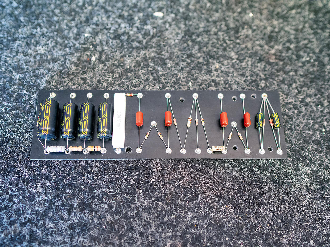
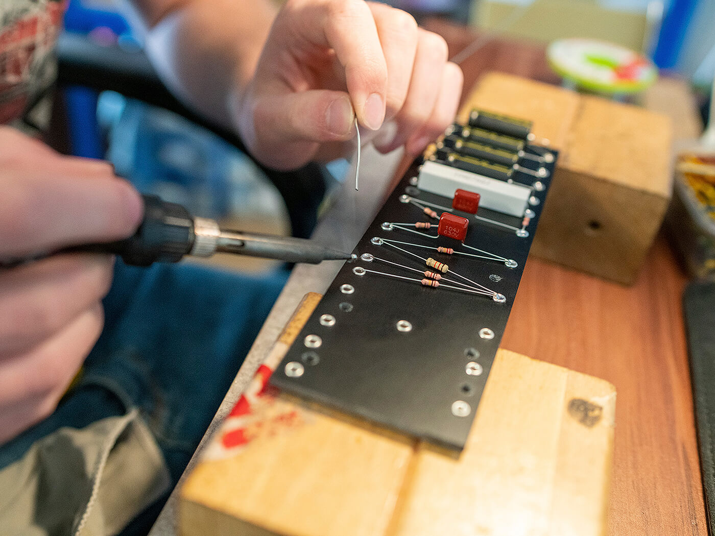
The completed board. The final result is clean and neat
Hi Chris, as a teenager, I used to own a Gibson EH-185 amplifier and loved it. They fetch quite the price today – could you build a clone from scratch? And how would you do it?
– Ken, Plymouth
Chris Fantana: Hi Ken, I often get asked about the EH-185 by jazz players and it’s always been on my ‘to do’ list. There’s no time better than the present to get cracking on a long-procrastinated project, so let’s have a go.
- READ MORE: How do I build a Gibson EH-185 clone? (Part Two)
- READ MORE: How do I build a Gibson EH-185 clone? (Part Three)
My goal for this project, in the short-term at least, is to achieve what we call ‘proof of concept’ – a working prototype that answers the simple question, “can it be done?”. Unfortunately, I don’t have an EH-185 here at the workshop so my only tonal reference will be videos found on the internet and similar. A quick search online reveals a hand-drawn schematic for the amp in question, which is a great starting point and will allow me to see the basic circuit architecture.
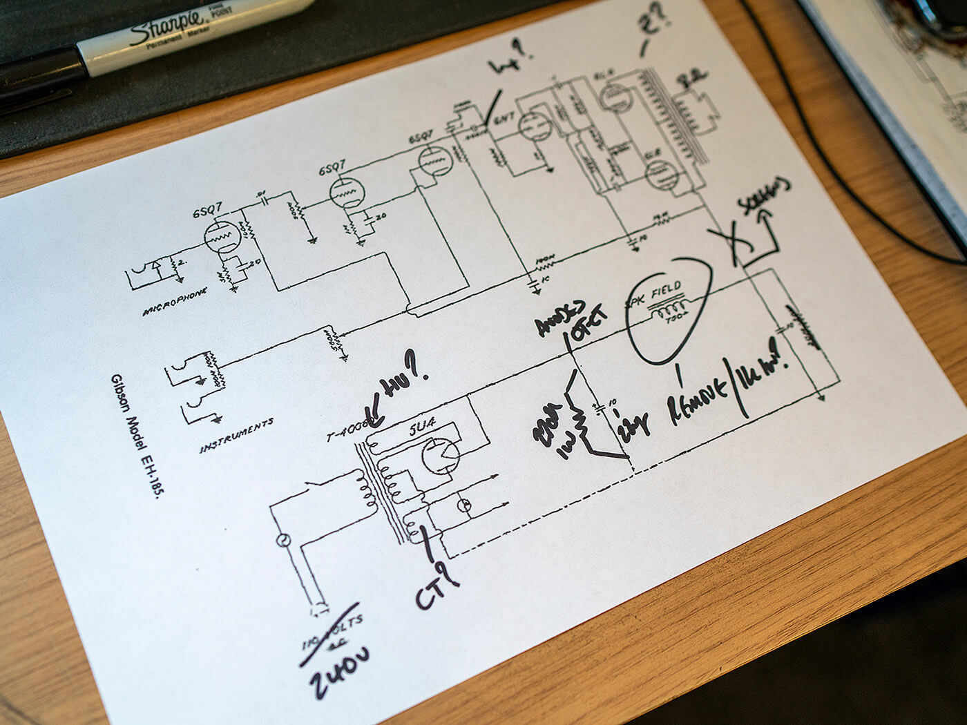
I start by studying the schematic, looking for anything unusual that might cause problems down the line. The EH-185 is quite a simple amplifier with very little between the inputs and the speaker. The amp has two channels, one labelled ‘microphone’ and the other ‘instruments’. I would imagine that the designers envisaged that the user could use the EH-185 for both their guitar and vocals at the same time. The microphone channel has a single input socket, while there are two inputs on the instrument channel, possibly allowing a second guitar player to plug-in too.
The mic channel uses two 6SQ7 octal preamp valves before the phase inverter, yet the instrument channel only has one stage of amplification, again a 6SQ7. A rarely used 6N7 octal valve is used in this ‘paraphase’ phase inverter circuit, similar to that found in the 5A3 TV front Fender Deluxe. Two cathode-biased 6L6s power valves are found in the output section, generating a stated output of 20-watts, although I suspect that might be quite optimistic. All fairly standard stuff so far until we reach the single 12-inch speaker which is a very old field coil design. Rather than the permanent magnet speakers found everywhere today, these speakers use the high-voltage DC from the power supply to energise the speaker. Remember electro-magnets from science class? Exactly that.
To keep things simple, we won’t use an FC speaker but a more modern PM unit instead. This is generally quite easy to do although, in the EH-185 circuit, the field coil has a secondary function as a choke in the high voltage rail to help regulate current. We’ll have to carefully design our new high voltage supply to allow for the changes in both voltage and current draw.
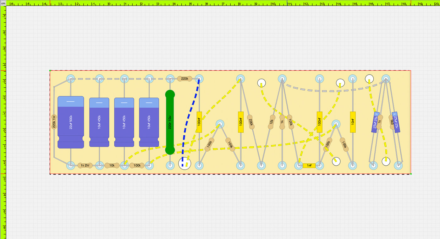
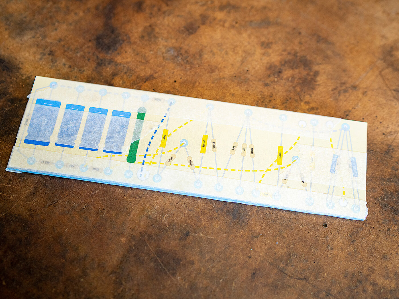
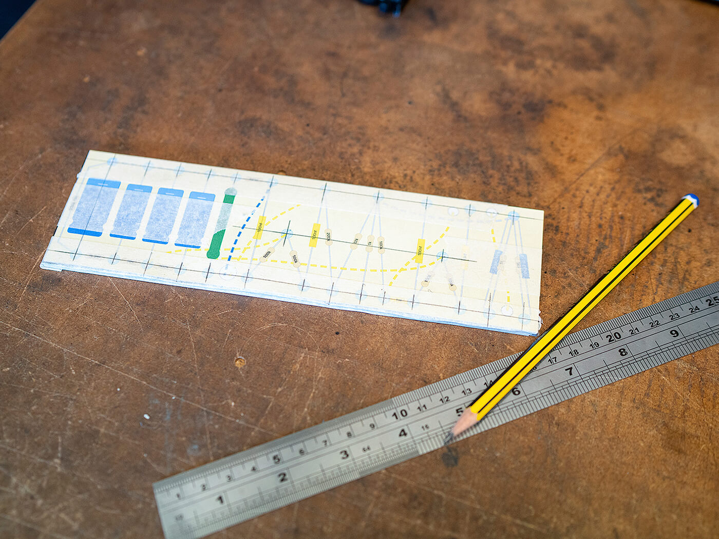
My first task is to convert this schematic into a chassis layout. I’m not going to copy the original layout but draw my own instead. This has two benefits, the first is that I can choose to optimise the position of every component and wire for the best design possible. The second is that I won’t be copying any mistakes or bad practices that might be found in the original layout.
I like to have all of my components – or as many as possible – located on a single centralised eyelet board with flying leads connecting everything together. I generally have the power supply on the left-hand side of the board and the preamp section on the right. This keeps the most noise-sensitive part of the circuit as far away from the power supply as I can get it. Even today, mains AC is dirty enough to cause noise problems in a guitar amplifier, so I must do everything that I can to keep the circuit quiet.
The layout is quite easy to do and I’ve drawn similar circuits before. As this amplifier was designed pre-WW2, many of the resistor and capacitor values are no longer in production after the standardisation in 1952. For this build, we’ll use the nearest modern ‘standard’ values and tweak later. With that in mind, the board layout is done in such a way that replacing any component in the future will be a simple task with easy access to every solder joint.
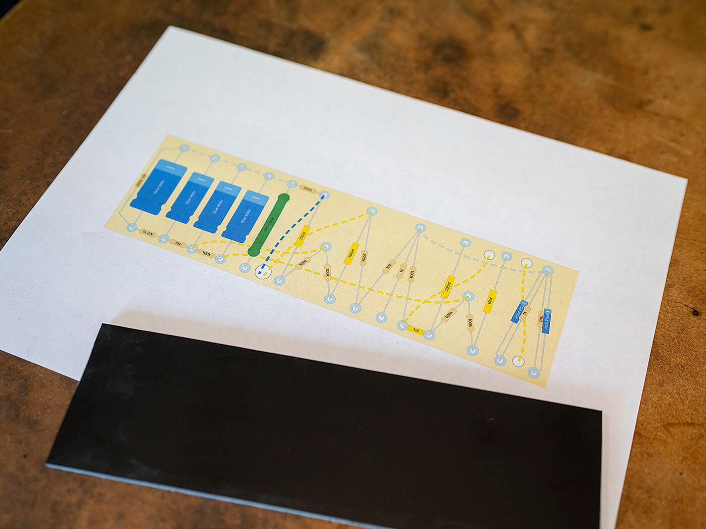
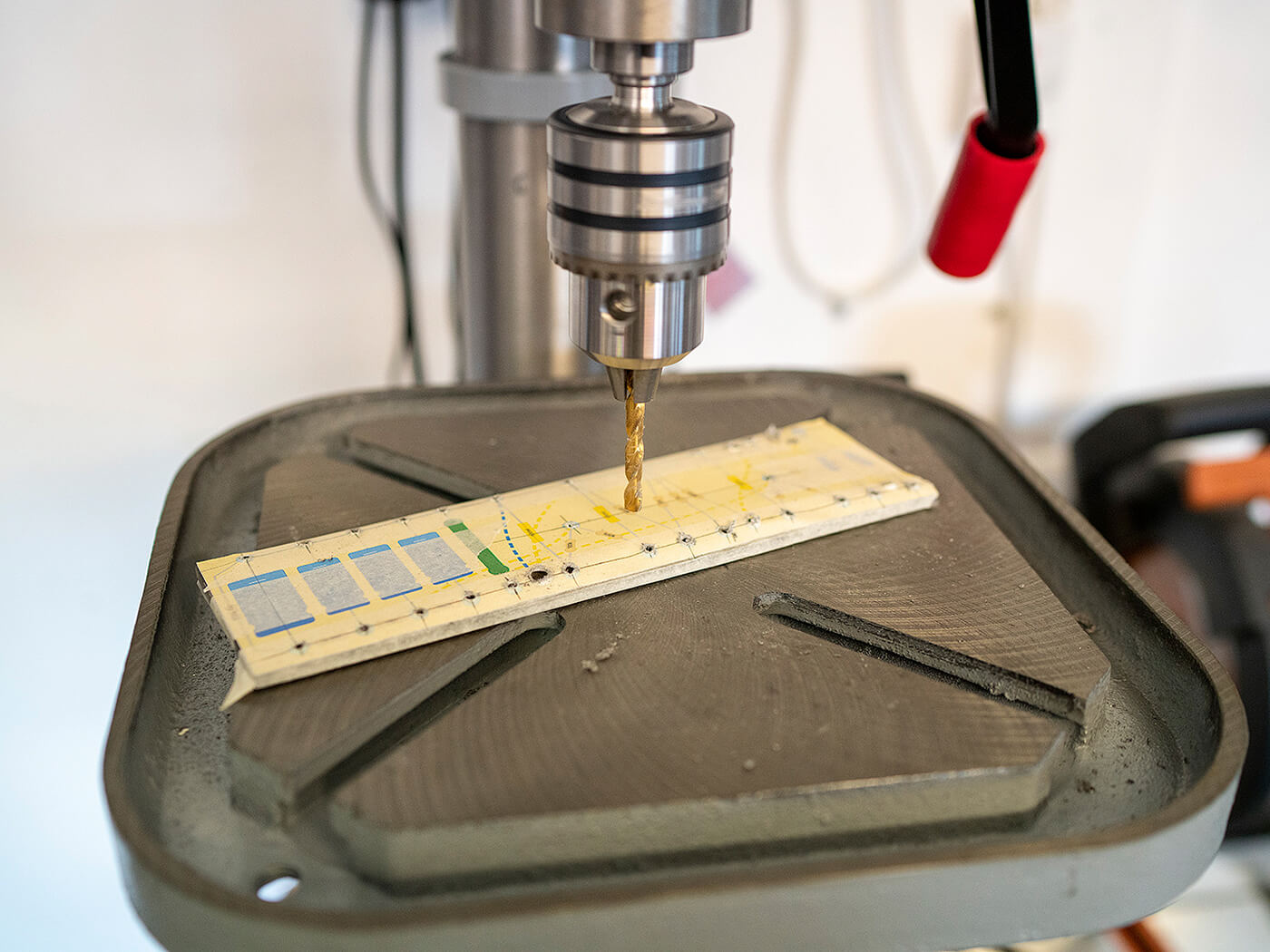
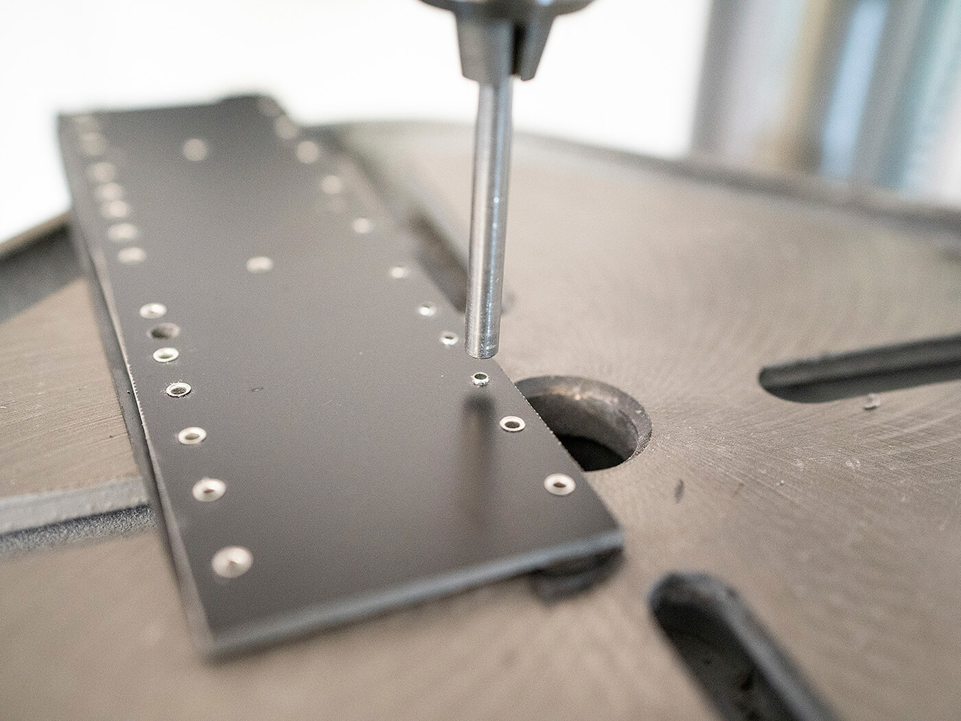
Once the layout is completed, I print it off and attach to the board material itself before drilling out the holes using a drill press. The eyelets are then placed into the appropriate holes and then swaged into position from the underside. Populating the 220x64mm board is done with nothing more than a pair of needle-nose pliers, a pair of snips, a soldering iron, and some high-quality lead-free solder. The components are placed one at a time and I like to solder them in place as I go along.
Once everything is completed we can put the board to one side and focus our attention on to the next step of the build: the chassis. Come back next month to see how the build has progressed.
Visit riftamps.com to check out Rift’s range of British boutique amplifiers.