Related Tags
Amp FAQ: How do I build a Gibson EH-185 clone from scratch? (Part Two)
Chris Fantana’s Gibson EH-185 clone build progresses to the chassis.
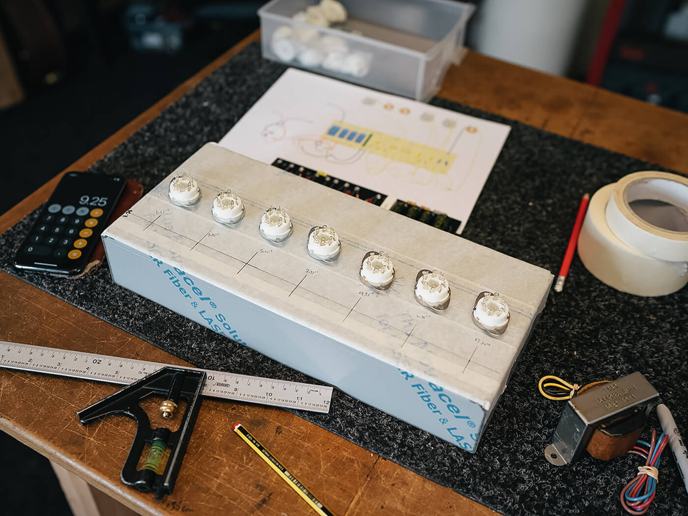
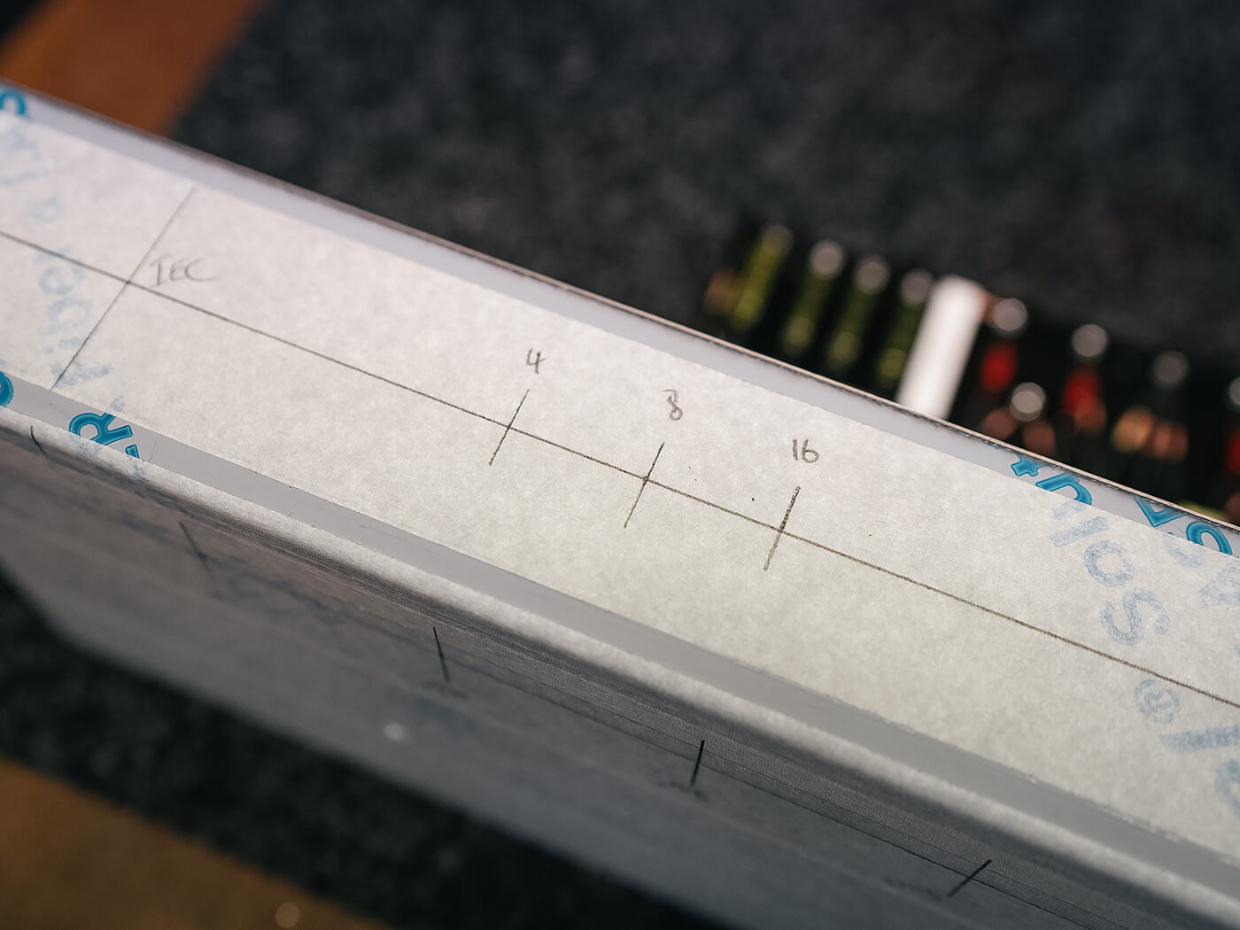
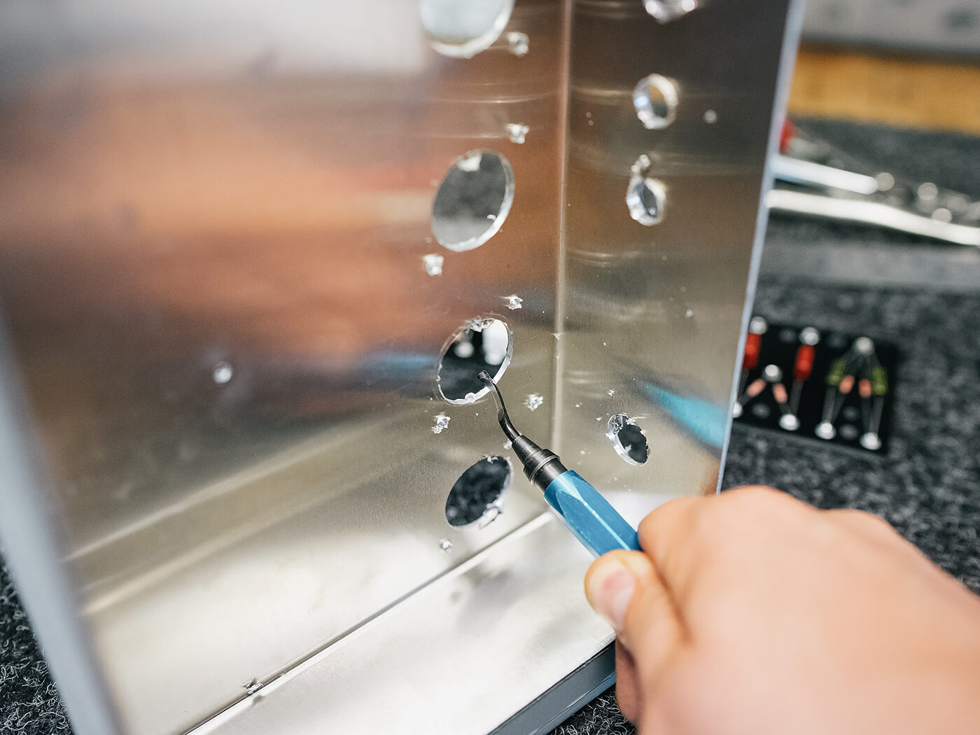
Marking the position of the valve sockets. All images: Chris Fantana
Last time around, I designed and populated the component board, so I now need to start work on the chassis layout. I always like to draw my designs using 1:1 scale on the computer, and as such, I need to know the chassis dimensions to ensure that everything fits perfectly.
- READ MORE: How do I build a Gibson EH-185 clone? (Part One)
- READ MORE: How do I build a Gibson EH-185 clone? (Part Three)
Tubetown.de sells a range of ‘blank’ aluminium chassis in various sizes and the 365 x 160 x 65mm unit (TT- CH062) is perfectly sized for a small project like this, although with seven valves to incorporate it might be a squeeze.
With the valves on one side of the board and the controls on the other side, I can start to draw on my flying leads connecting everything together. The layout is only a rough version at the moment, allowing me to gauge the location of the components relative to each other, along with indicating whether I might need to move things around to optimise the design.
There are a few improvements that I can make to the original circuit design, mainly from a reliability point fo view. Firstly, the 6L6 output valves do not have either control-grid or screen-grid stopper resistors. The former is used to prevent both parasitic oscillations and to also help smooth out unpleasant distortion under overdrive. The latter is used to protect the screen-grid from over-dissipation when the valve is overdriven – a valve-killer for sure. I’ve chosen nominal values of 1k5 for the control-grids and 470r 1W for the screens, as a starting point.
There are other benefits to using stopper resistors in the amplifier, such as on the input stage to create an RC (low-pass) filter with the input capacitance of the first valve. This creates an RF attenuator for anything above our chosen cut-off point, in this case, 20kHz or so.
Secondly, I’ve added some protection diodes (1N4007) in series with the high-voltage supply to the rectifier valve. These protect both the circuit and mains transformer from damage should the valve fail. For only a couple of pence each, it’s a no-brainer.
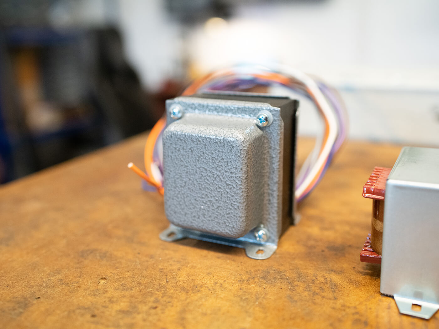
Transformers
During my research into the EH-185, I’ve found that detailed information about the transformers is limited, at best. The schematic that I have gives a model number for the mains unit, but not the output. Further searches on the internet still reveal little to no concrete evidence and the information gleaned from forums and the like seem to be contradictory. Fortunately, designing a 6L6-based output stage and power supply to produce 20 watts is quite an easy affair, providing you know how to read the datasheets.
Let’s start with the power supply. Firstly, I need to know how much current I’ll need to switch on the valves. All of them except the 5U4 rectifier require a 6.3v supply. The two 6L6s need 900mA each, the three 6SQ7s use 300mA each, and the single 6N7 needs 800mA. Add those together and we get a total of 3.5A. The 5U4 needs 5v at 3A, so that’s easy.
Finally, we need to choose our high-voltage winding. I’d like to have around 350v on the anodes (plates) of the 6L6s, this combined with an output transformer primary impedance of 6k6-8k should give us our 20w. The RCA datasheet for 6L6s recommends a 5k transformer at 270v for 17.5w so the extra grunt should get us to 20w easily.
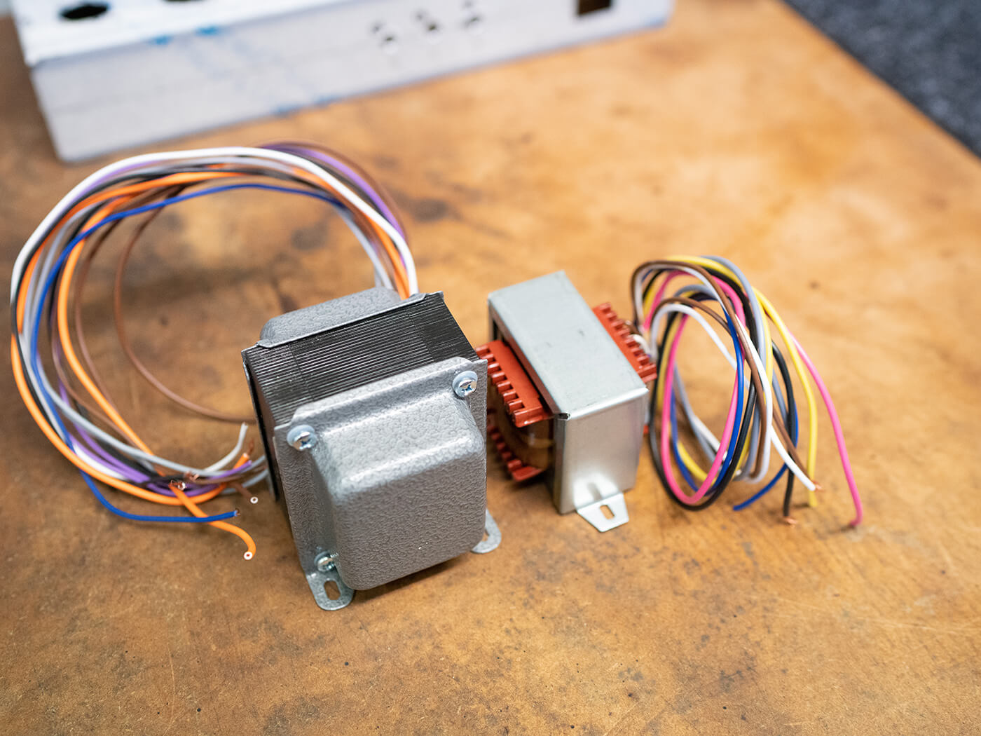
With this in mind and carefully calculating the power requirements for the rest of the circuit, I’ll need a high voltage supply of around 630v, rated at 140mA or more. Tube Town stocks a unit (TT-5E3-PW) rated for 640v at 150mA, with 6.3v 3.5A and 5v 3A windings too – perfect. It also sells an output transformer (TT-5E3-OT) rated at 25w with a primary impedance of 8k. It has 4, 8, and 16-ohm outputs so we’ll have lots of options for speaker connections.
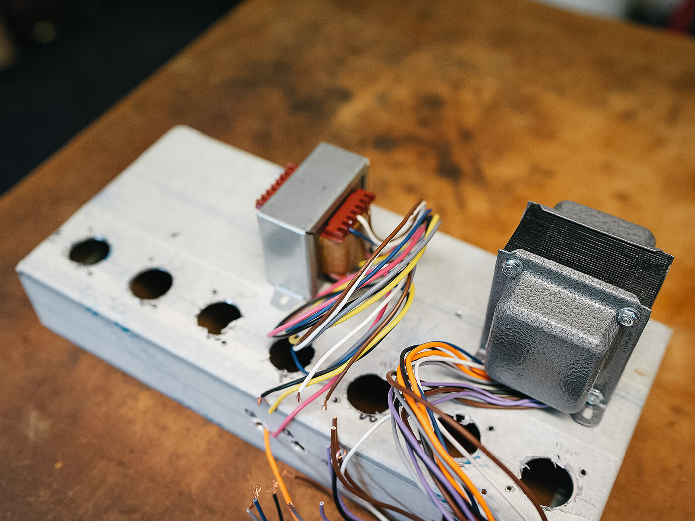
Chassis machining
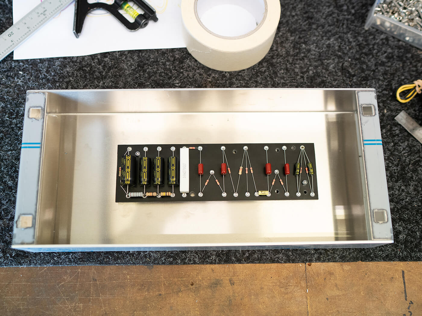
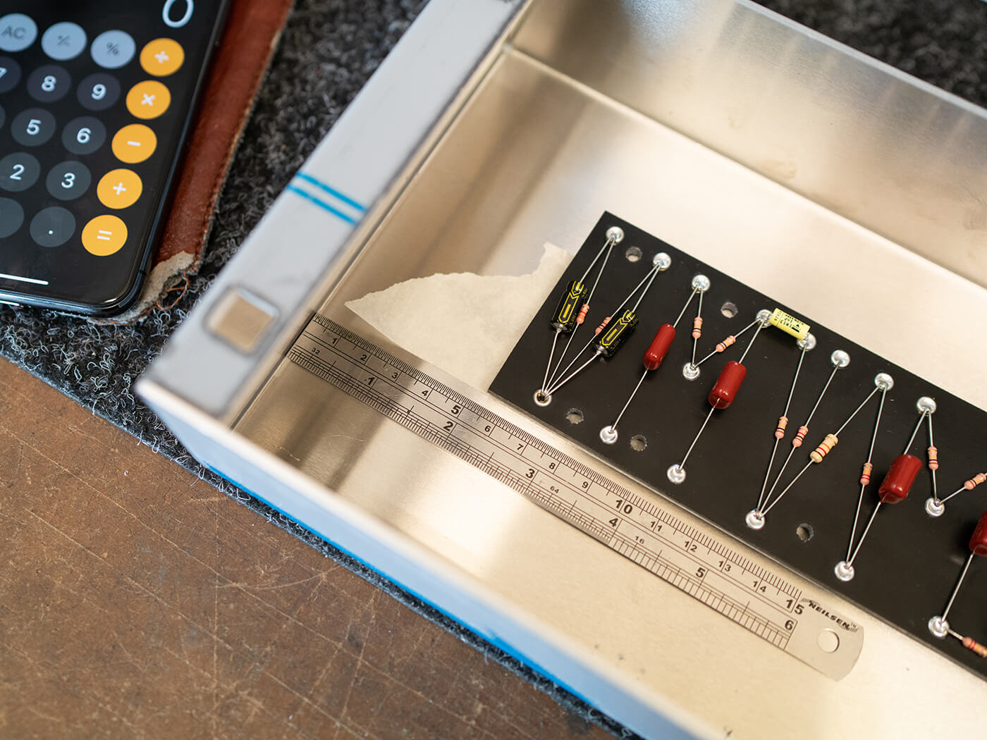
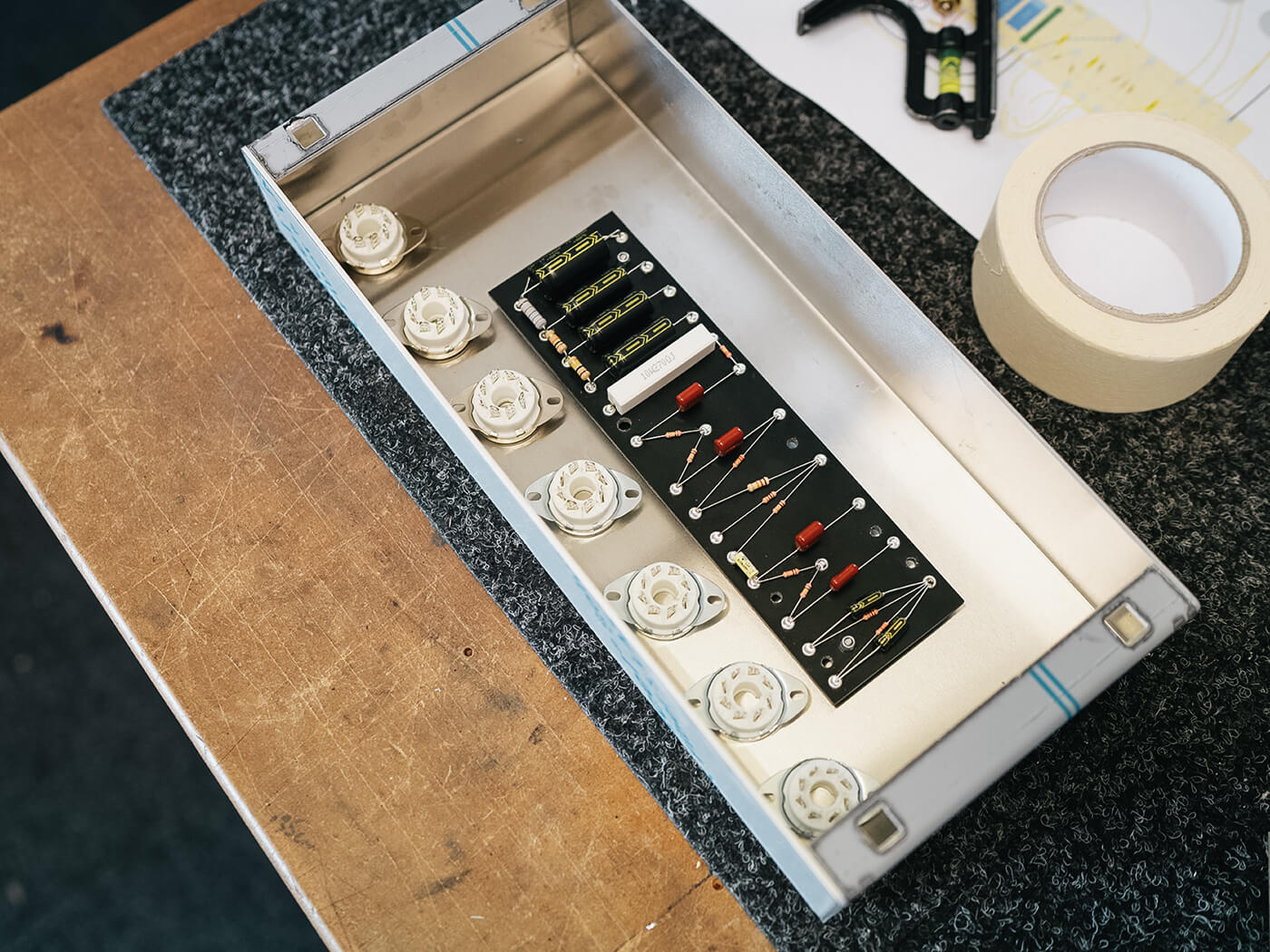
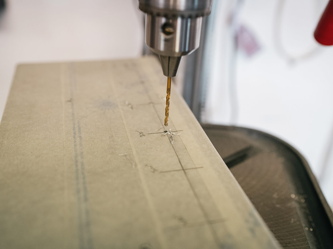
Now the real work begins! I start by choosing a mounting position for the component board inside the chassis. Using the seven octal valve sockets as a rough guide, I decide on a location that is 2-1/8” from the right-hand side, when viewed from the valve side of the chassis. On the Y-axis, the board sits directly central. I can now drill the M3 mounting holes for the board that will sit on 1/4” standoffs. With the board then set in place, I can start to finalise the position of the valve sockets.
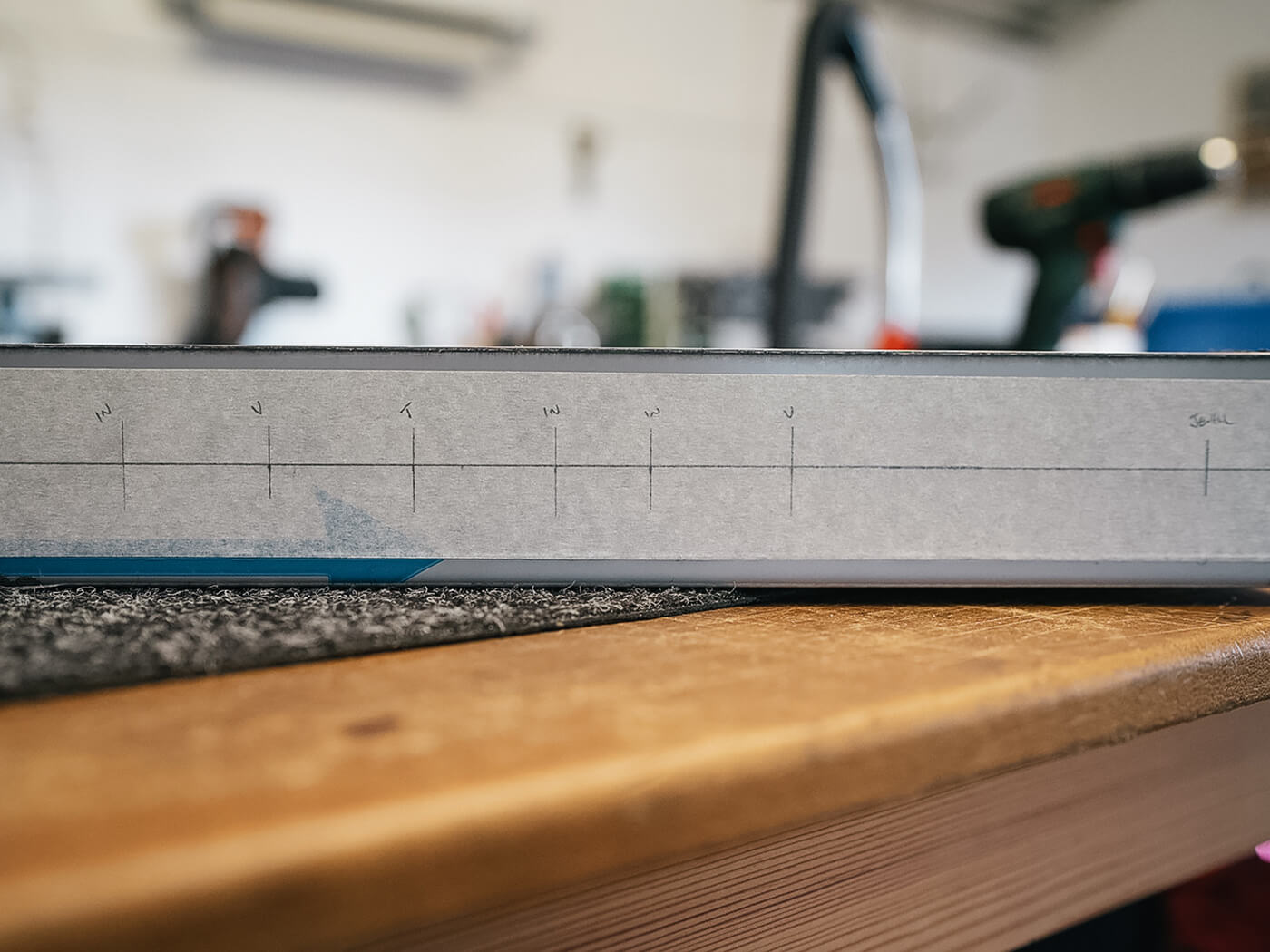
As a general rule of thumb, I like to position the sockets 1-1/4” from the rear of the chassis to allow adequate room for a neat lead dress. A datum line is drawn and then I can start to mark the positions along the length of the chassis. Checking the datasheets for each valve, I can find out the preferred mounting position and location for each, relative to another.
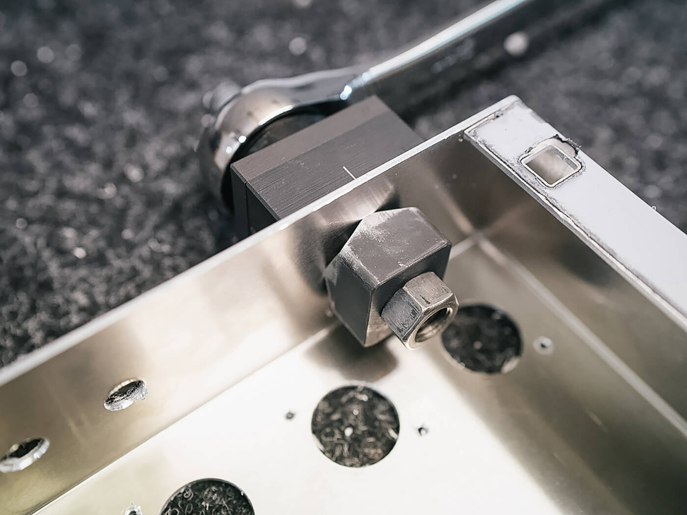
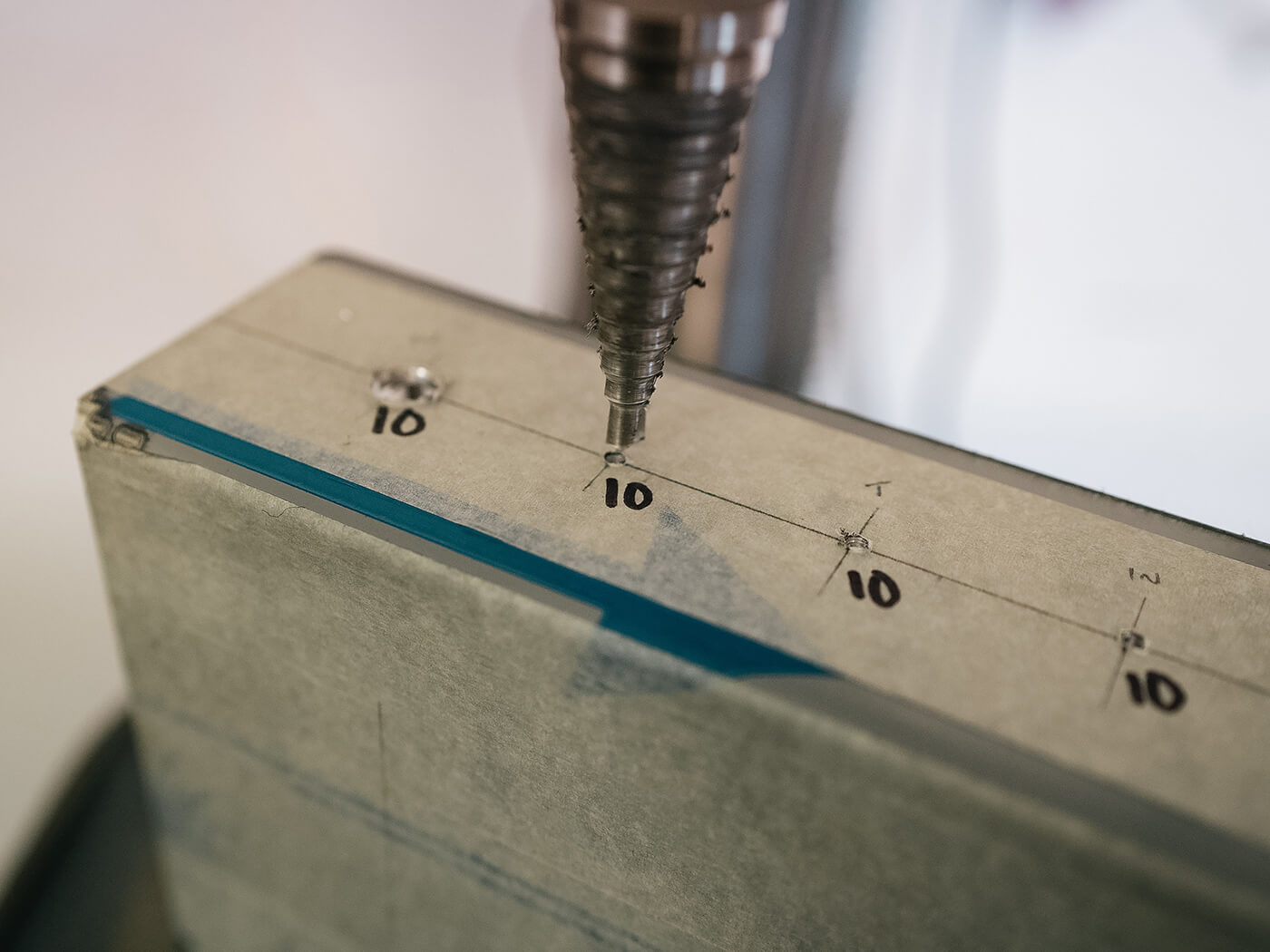
Some valves, such as the KT66 for example, require at least 2-1/2” distance between the mounting centres, in any orientation. In this case, there are no such restrictions, but a 2” gap is a good starting point, so that’s what I’ll use. The first valve will be 1-1/4” from the edge, and then the others at 2” intervals after that. With all of the sockets marked, I can now drill them out to the required size of 26mm.
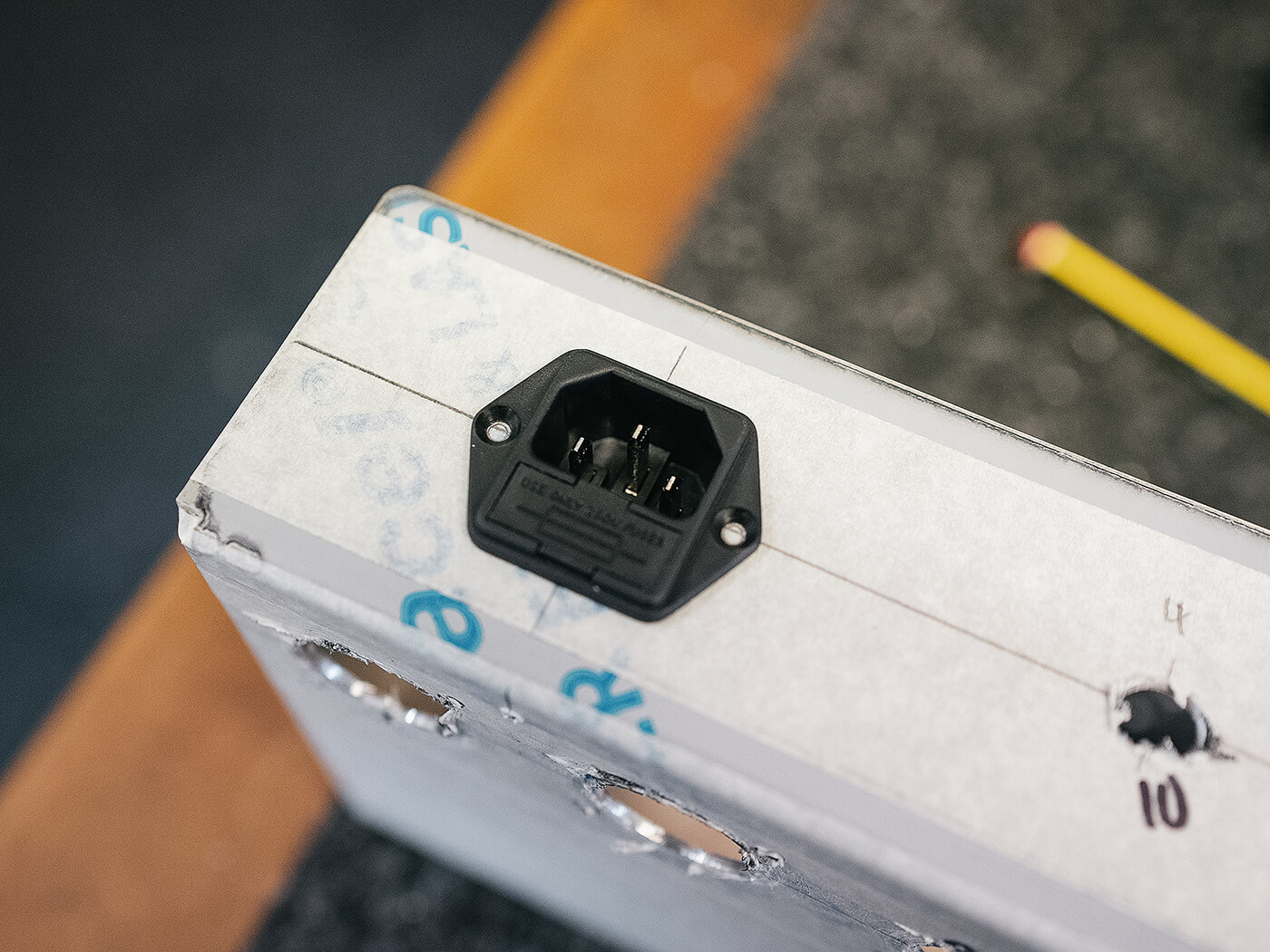
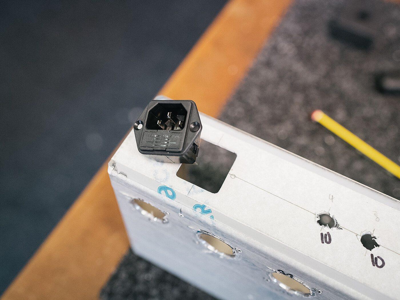
Using the same method as above, I mark the positions of both the front controls, the rear speaker sockets, and the location of the mains/fuse connector. These are then drilled and punched out to the required size, just as before.
That’s it for this month, and with some good progress made our EH-185 is slowly starting to take shape. Come back next time to see how the project develops.
Visit riftamps.com for more on Chris Fantana’s range of Brit-built boutique amplifiers.