Related Tags
How to build your own spring reverb unit
How to build an add-on tube-driven spring reverb module based on classic Ampeg and Swart-style circuitry that can be retrofitted to loads of different amplifiers.
All images by Huw Price
I’ve always had an uneasy relationship with reverb. I’m crazy about plate and spring reverb effects in the studio, and always have to take care not to overdo it. But when it comes to the traditional tube-driven spring reverb in most guitar amps, I’m less enthusiastic.
I may be in the minority, but when it comes to Fender reverbs in particular, I often find myself struggling to find that happy medium between too much and too little. There is, however, a style of amp reverb that really does work for me and I first encountered it when I got the chance to review a Swart amplifier.
Swart’s reverb really gels with the dry guitar signal to enhance it rather than drown it, and to my ears it sounds more like the AKG studio spring reverbs that I love so much. So the idea behind this project is to build a Swart-inspired reverb module that can be added to a wide variety of amps.
Neutral space
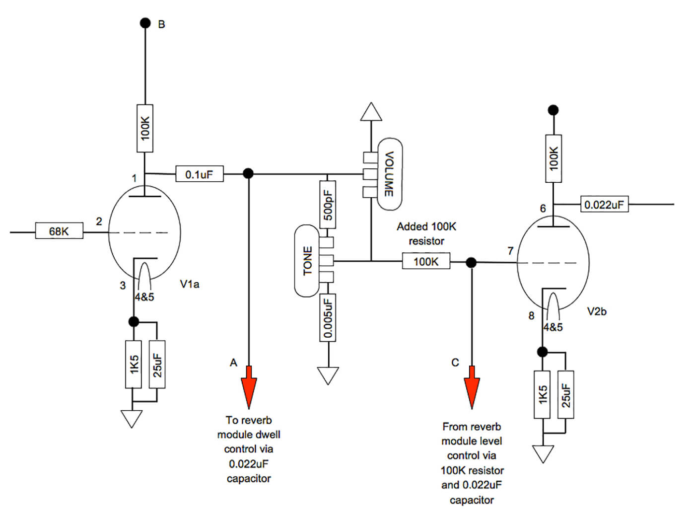
After checking various online schematics and reverse engineering a friend’s Swart, it appears the circuit is actually derived from vintage Ampeg designs. In 1960s Fenders, the reverb send comes after the tonestack, which means the signal already has a ‘smiley face’ mid-scooped frequency response before reaches the spring tank.
In contrast, the signal is sent to a Swart reverb immediately after the first gain stage. So, a nominally flat frequency signal goes to the reverb. Having passed through the reverb circuitry and spring tank, the wet and dry signals re-convene via 100K mixer resistors. These come just before the second gain stage and have very little effect on signal levels – unlike the whopping 3M3 resistor separating the send and return signals in some Fenders.
This makes the Swart reverb design fully independent, and the amp’s volume control operates only on the dry signal. You can even turn the volume right down and listen to the reverb effect on its own.
The Ampeg Reverberocket and Swart reverbs have no transformer and use a single tube. Ampeg employed an octal base 6SN7 dual triode and Swart use a 9-pin 12DW7 – aka ECC832 – with the one triode being equivalent to a 12AU7 (ECC82) and the other a 12AX7 (ECC83). The low gain/high current 12AU7 side drives the spring tank and the higher gain 12AX7 side is used to recover the signal level that’s lost through the tank.
Parts smarts
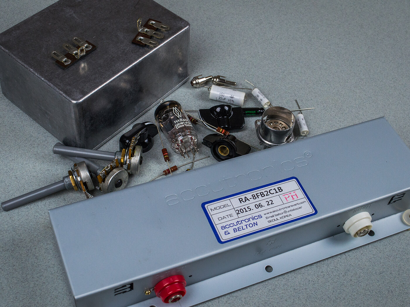
Another advantage of the Ampeg/Swart approach is the relatively small number of parts required. Besides an enclosure, a handful of components and a valve socket, the only costly item is the reverb tank itself.
There’s more to spring reverb tanks than meets the eye and you must choose the right one for any particular application. Fortunately, the seven digit code on all spring tanks provides the information you need.
Swart uses an 8FB3C1B. The first digit tells you the size of the tank and the number of springs inside. Type 8 is the smallest and it contains three springs, which makes it ideal for Swart’s compact cabinets. The four-spring Type 4 and six-spring Type 9 are intended for larger cabinets.
The second and third digits give you the input and output impedances respectively and FB denotes 1,475-ohm and 2,250-ohm. Depending on the circuit you’re using, and whether there’s a transformer involved, the impedance requirements will differ.
The following digit will be a 1, 2 or 3, which gives you the tank’s decay time in ascending order – from 1.2 seconds to four seconds. Next up is the connector code, which tells you if the input, output, both or neither is grounded. Apparently, the Ampeg/Swart circuit requires an isolated input and a grounded output.
The penultimate digit tells us there’s no locking device for the springs and the final digit tells us how the tank needs to be mounted. In this case, the ‘B’ signifies that it should be fixed horizontally with the open side downwards.
The 8FB3C1B isn’t as easy to find as some, and all the European retailers were out of stock at the time of writing. Rather than order one from the US, I bought an Accutronics 8FB2C1B and I’m hoping the shorter 1.75-3.00 second decay time will suit me fine. Armed with this knowledge, you can also choose a compatible tank for your amp if you don�’t like the character of the one that came with it.
Space control
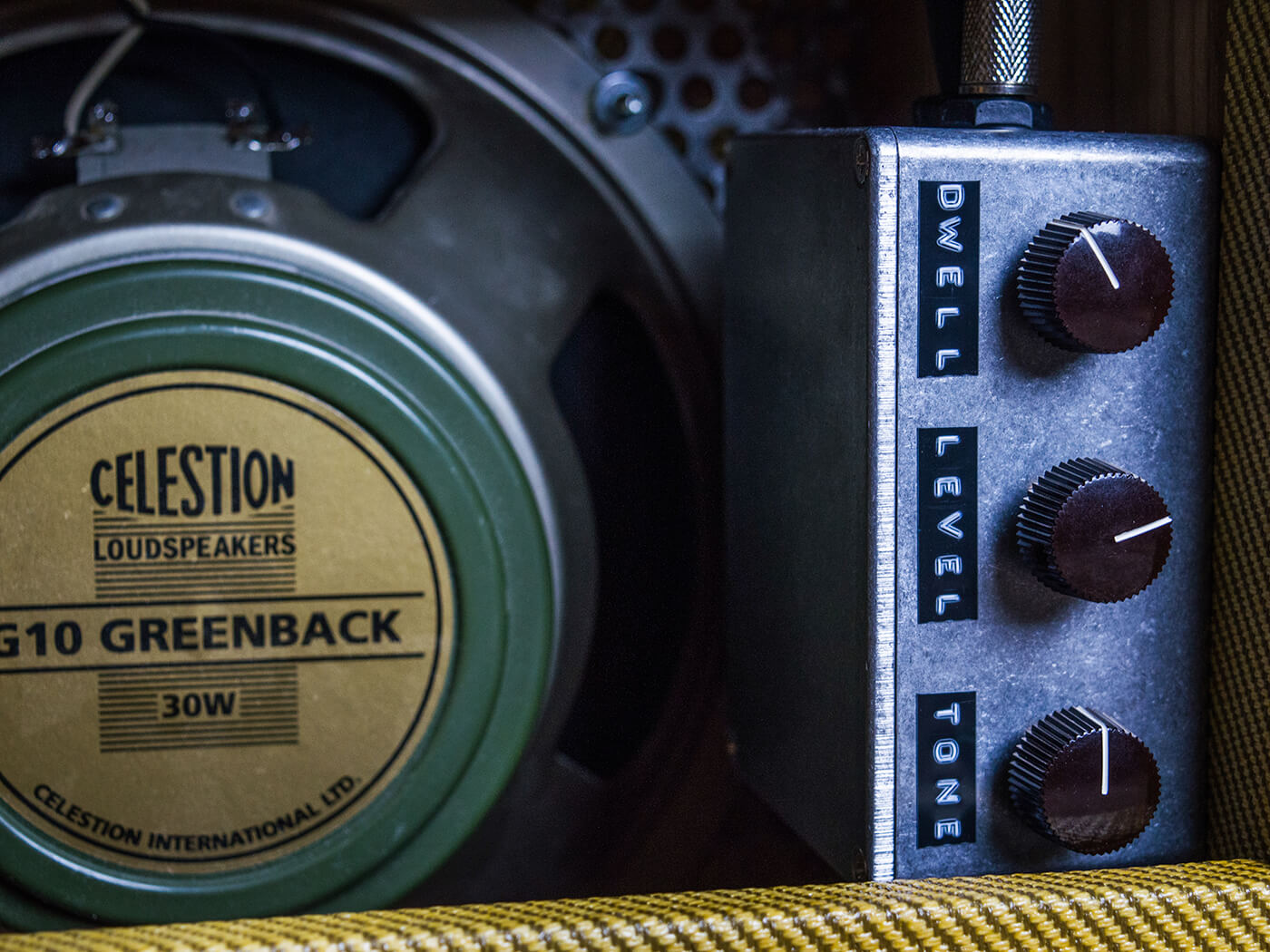
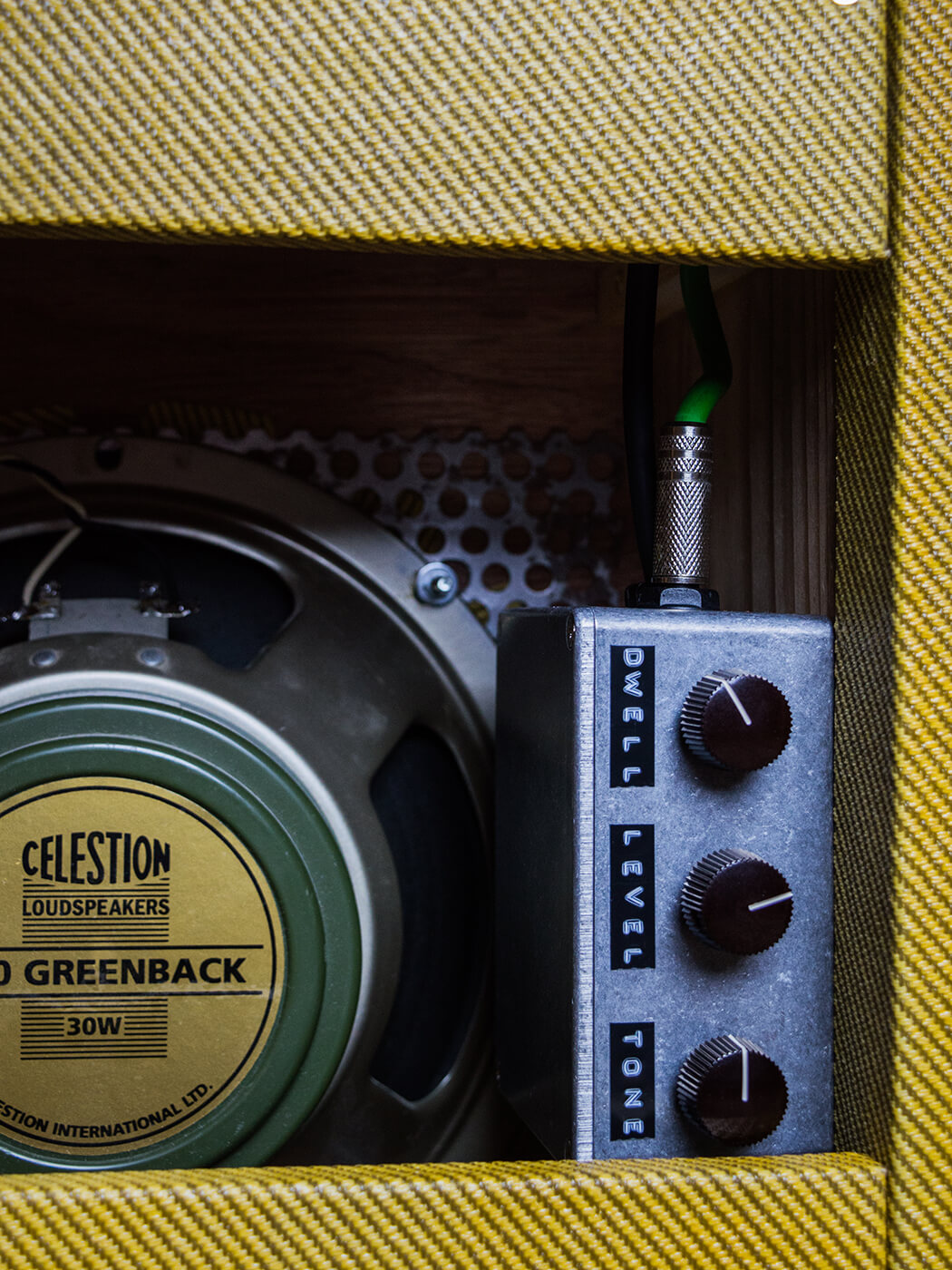
Space is restricted on amplifier control panels, so reverb level is usually the only control you get. But building a reverb module means you can add a couple of additional controls, and I’m adapting the circuit for dwell and tone, as well as level. ‘Dwell’ sets the signal level entering the reverb circuit, and tone is a simple treble roll-off.

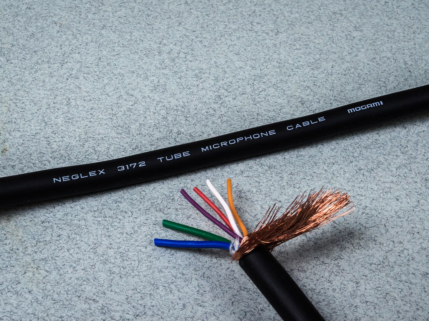
Multiple connections are required for the HT and heater voltages, input and output signals and grounding. I decide to use a length of Mogami Neglex 3172 tube microphone cable, which is widely available online. It’s made for exactly the same purpose – namely connecting preamp circuitry and audio signals to a remote power supply.
As such, the colour-coded wires are rated to cope with high current in the case of heater supplies and high voltage for the plates, and everything is screened to minimise noise. I’ll be hard-wiring this cable to the internal components and securing the cable to the module enclosure using a strain relief clip.
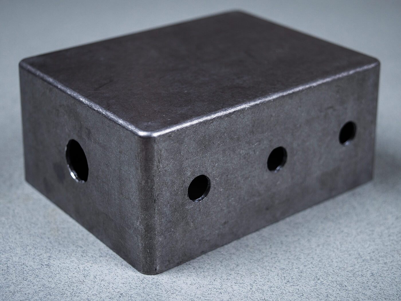
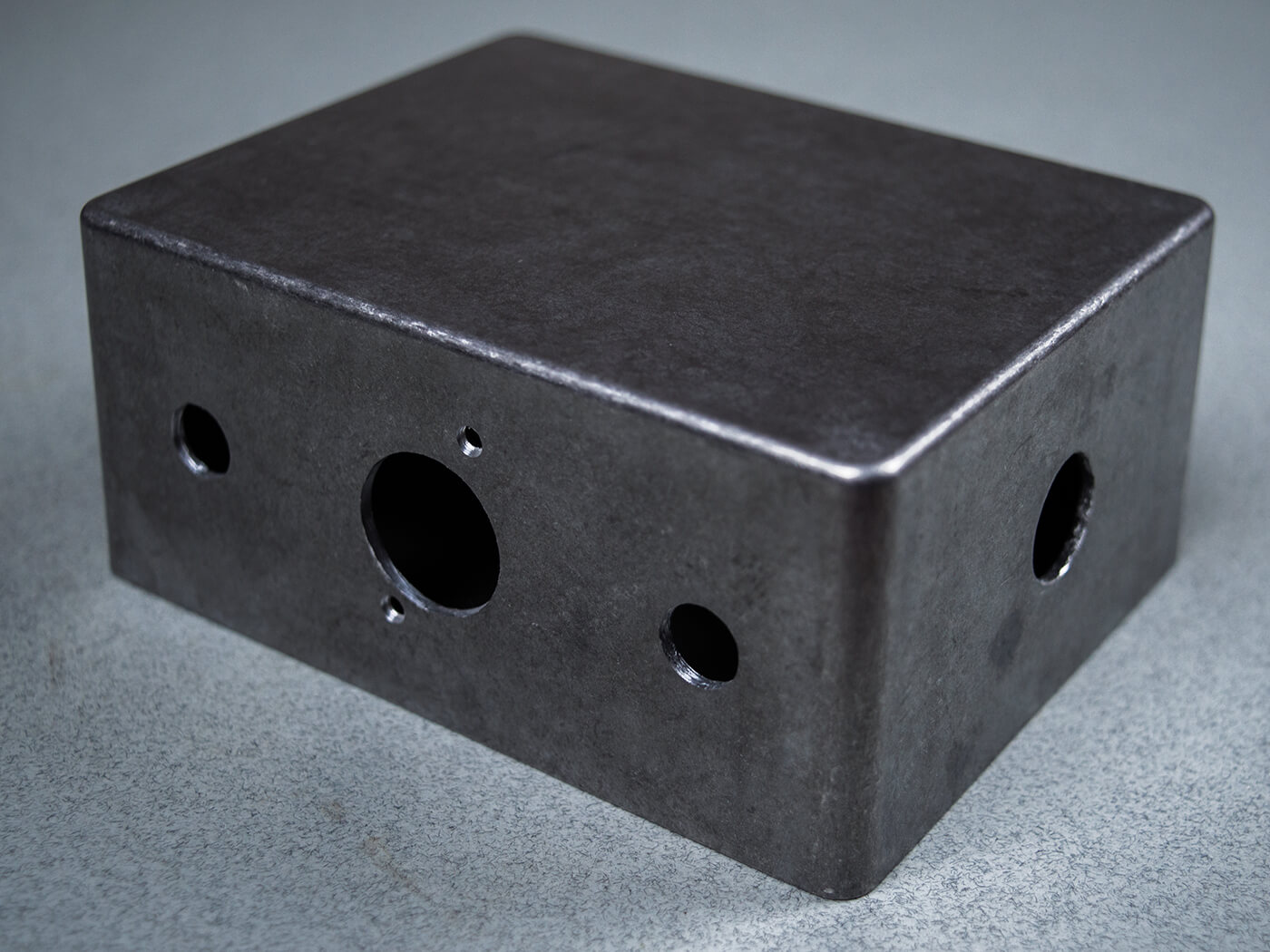
I mark up the positions for the potentiometers, cable, valve base and RCA socket holes, and drill them all to size using conventional metal bits plus a step cutter for the valve socket hole. I also drill a hole to mount a three-way tag strip onto the rear surface of the enclosure.
Loading up
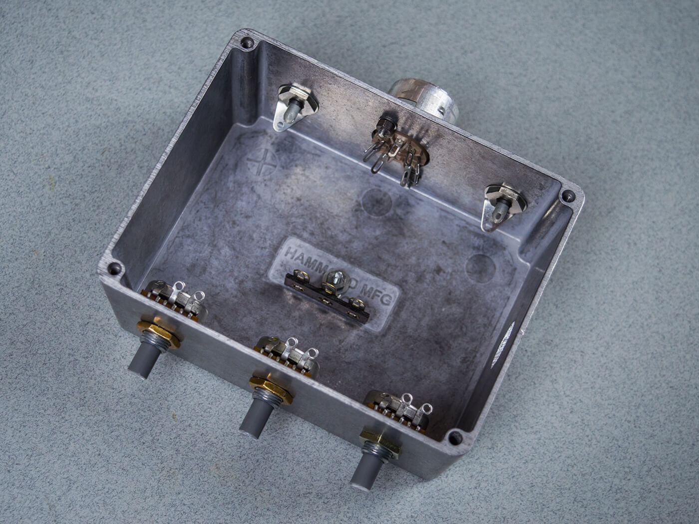
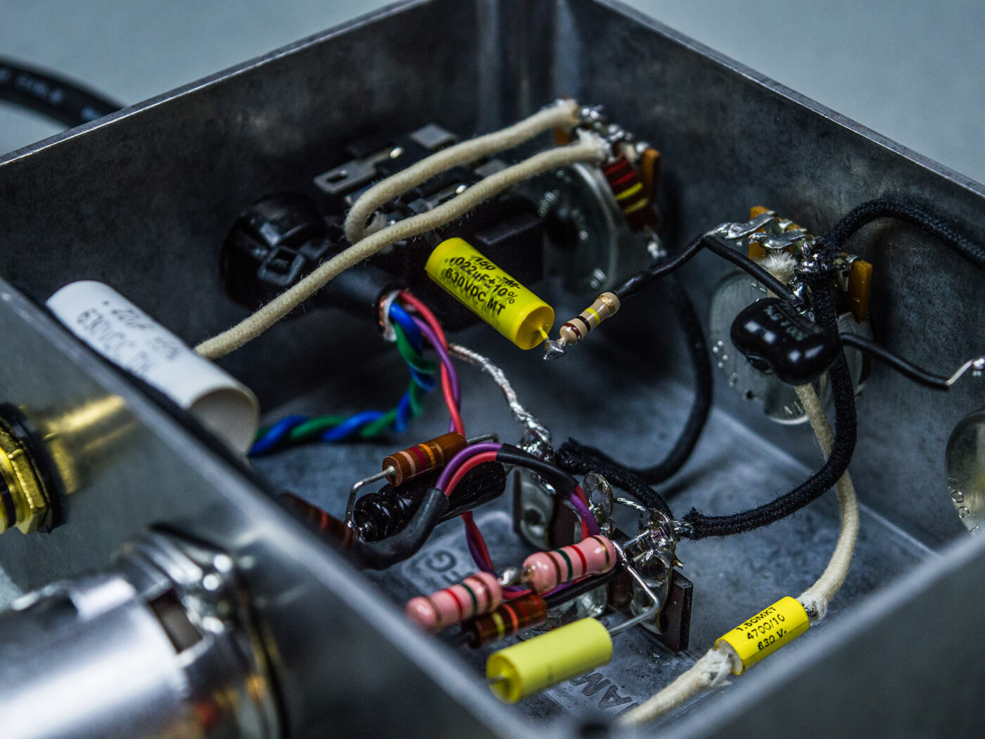
The assembly process will be familiar to anybody who has built effects pedals. I begin by loading up the enclosure with the pots, valve base and RCA sockets for the tank send and returns. The three-tag strip is mounted close to the valve base because it will be used for the ground connections off the 12DW7’s cathodes. Sufficient space is allowed for the cathode resistors and bypass capacitors.
I remove about 100mm of the Mogami cable to expose the wires and secure the cable to the enclosure with a strain-relief clip. The blue and green wires are twisted together, routed around the edge of the enclosure and soldered to the heater pins – blue to pins four and five – and green to pin nine.
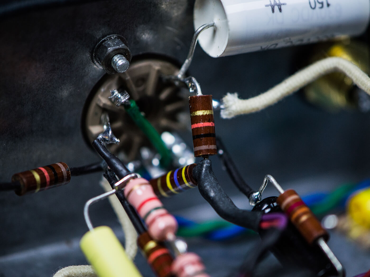
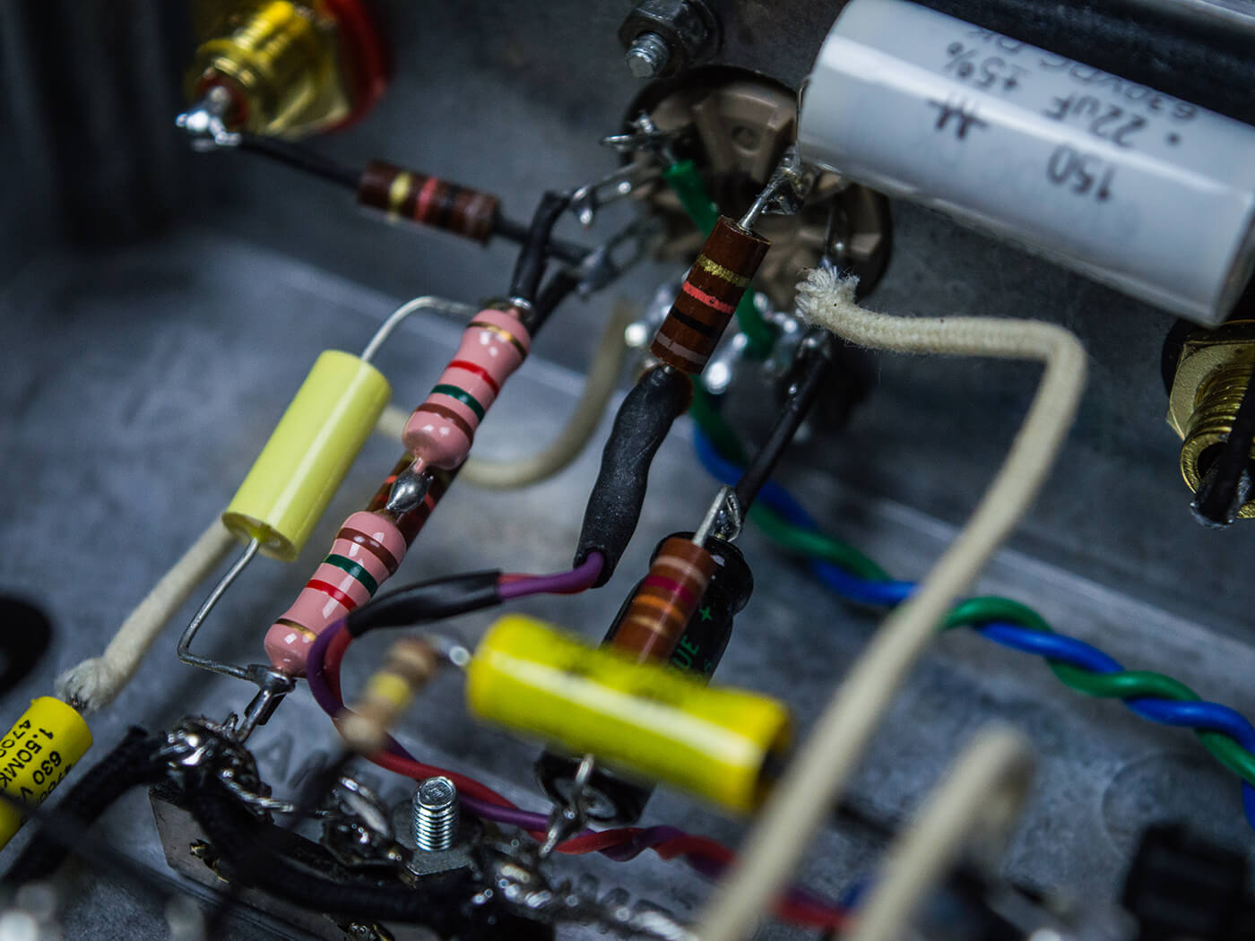
Given the circuit’s simplicity, it makes sense to wire it point-to-point rather than fabricate a circuit board. The plate resistors are soldered straight onto pins one and six, and I twist the red and purple wires together to carry the HT voltage.
From there, it’s simply a case of installing the components and hooking up the controls. The most important connection of all is the ground wire, which in this case is the shield of the Mogami cable, and it’s absolutely vital for safety.
Ho hum…
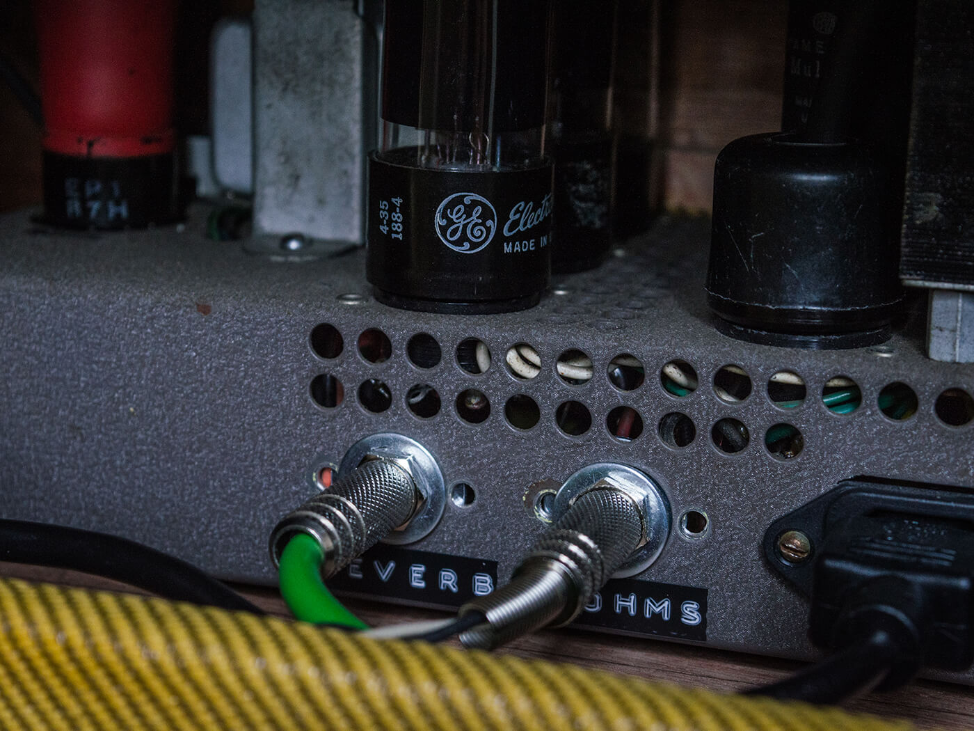
With assembly complete, the next step is to test the module. I decide the ample space inside my Vibro Champ will make this process a lot easier than the rat’s nest of wiring inside the Filmosound conversion, which I eventually hope to pair up with this reverb.
At this point the Mogami wires are connected to the Vibro Champ’s circuitry ‘on the fly’, with the heater wire soldered to the heater tags on the 6V6 valve base, and the HT voltage wires onto the power supply after the third stage of filtering.
In tube microphones, the white and orange wires are used to carry audio signals, so the send wire is connected to the plate of V1 (pin one) via a 0.022µF capacitor. A small mod is needed for the return connection, and I solder a 100K resistor between the tonestack output and the grid of the following valve stage (pin seven).
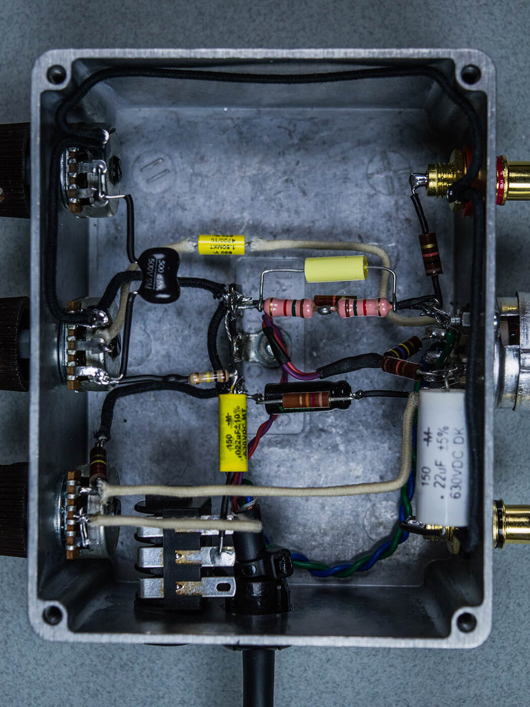
Inside the enclosure, the output of the level pot has a 100K resistor and a 0.022µF capacitor in series. The two 100Ks are mixer resistors for the dry and wet signals. The Mogami ground wire is soldered to the chassis ground of the Vibro Champ.
Using a circuit breaker and my ‘light bulb’ current limiter, I switch on and measure the voltages inside the module. It all looks good, the valve is glowing orange, and the reverb is working, albeit with slightly more hum than I’m prepared to tolerate.
Sound ground
I’ve often wondered why very few people build these apparently simple reverb module retrofits. Perhaps it’s because getting the grounding scheme absolutely right is vital for keeping hum at acceptable levels. Further research indicates that grounding the circuit at a single point seems to be the key.
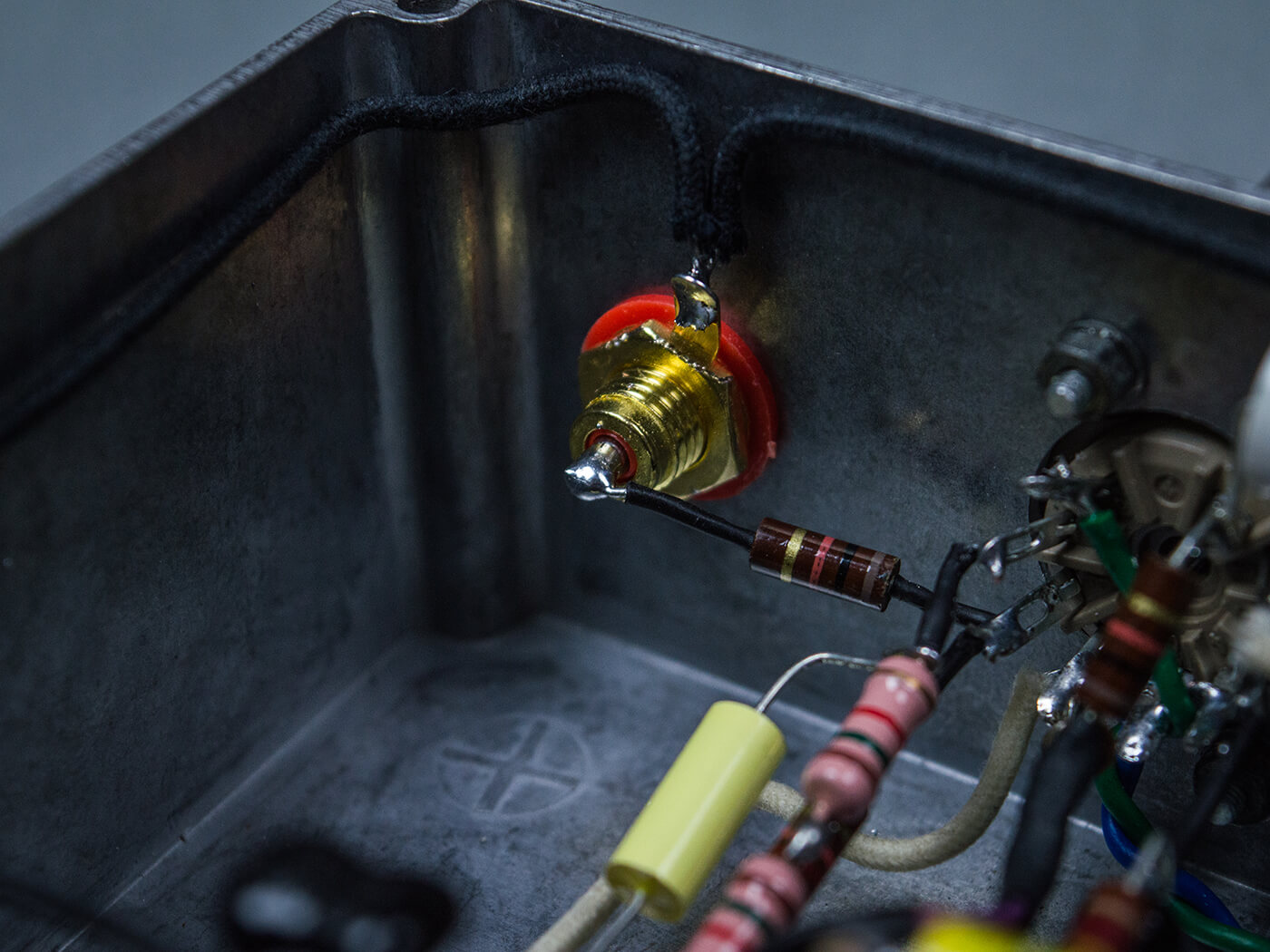
Do not ground RCA sockets directly to the enclosure or solder the potentiometer grounds onto the casings. Instead, I change the first pair of RCA connectors that are used for the tank send and returns for isolated RCAs. All the circuit ground connections are soldered to the tag strip – with all three tags linked together – and the tag strip is connected to the enclosure via its fixing screw.
The Mogami screen wire is also soldered onto the tag strip inside the module. At the other end it’s soldered to the chassis ground inside the amplifier itself and that’s the single connection for every grounded point in the reverb module. I also find that using a separate cable for the module send and returns is preferable to routing the signal wires through the Mogami cable – along with the heater and HT voltage wires.
For this, I mount an isolated stereo jack socket onto the module enclosure and it results in the lowest noise. I won’t claim this reverb is entirely hum and hiss free, but the noise floor is pretty much equivalent to a typical Fender amp reverb – and better than some.
Using a 4700µF capacitor between pin six of the 12DW7 and the level control also blocks low-frequency sonic garbage. You can increase the value if you prefer more low-frequency content in your reverb, but you may get more hum, too.
Final fitting
Having enjoyed the novelty of a Vibro Champ Reverb – albeit with the vibrato valve removed to ensure the power transformer isn’t subjected to excessive current draw – it’s time to complete the project by hooking it up to my Filmosound conversion.
In the process of re-purposing the amp for guitar use, one of the three 6V6s isn’t used. The HT and heater connections inside the amp remain connected to the empty socket, so I can solder an octal plug onto the end of the Mogami cable and make the power and ground connections by plugging it into the unused 6V6 socket. Leak hi-fi power amplifiers and preamps were connected in exactly the same way, and I can be confident that the Filmosound power transformer is up to the task because 6V6s draw more current than 12DW7s.
I also need to install an open-frame stereo jack socket for the audio send and return cable. Rather than drill a hole in the chassis, I decide to disconnect the unused 16-ohm speaker socket, remove the mono jack socket and use the vacant hole for the reverb audio wiring with a stereo jack socket.
I screw the module onto the inside wall of the cabinet and place the tank onto the cabinet base for testing. The reverb is exactly what I had hoped for and the added dwell and tone controls are well worth having. It’s a big, soupy three-dimensional sort of reverb and I find it a lot more versatile than a regular amp type ’verb – it can be very subtle as well as cavernous.
With the tone control rolled back, it’s dark and moody, but turn the tone the other way and it can be splashy, too. The dwell control can be set for clean reverb tones, but there’s also the possibility of pushing the reverb into overdrive and getting even more splashy and surfy.
Having decided that it’s a keeper, the plan is to upgrade the power connections by replacing the 6V6 socket with a four-pin cannon connector that will be safer and easier to use. I’ll also buy a bag for the tank, rather than screw it down straight away. Some bespoke RCA-to-RCA cables to link the module to the tank are also needed and I’ll add a jack socket for an on/off footswitch at some point.
Again, it’s worth saying that this reverb can be retrofitted to most tweed-style amps, as well as some Gibson, Vox and Marshall-style circuits – so long as the power transformer can cope with the current draw of an extra valve.
This is not a beginner’s level project, but it should be easy enough for anybody with a bit of experience in valve electronics. Always remember that the voltages in these circuits are dangerous and potentially lethal, so if you decide to try this one, you do so at your own risk. Happy surfing!
Parts list
Resistors:
- 100K x 2
- 220K
- 22K
- 1.2K
- 470K
- 3K
- 10K
Capacitors:
- 0.22µF
- 0.022µF x 2
- 0.1µF
- 25µF/25v electrolytic
- 4700pF
- 500pF
Potentiometers:
- 1M x 2
- 220K
Miscellaneous:
- Aluminium enclosure
- 12DW7 valve
- 2x isolated RCA sockets
- 9-pin valve socket
- Isolated stereo jack socket
- 3-way tag strip
- 3x knobs
- Strain relief clip for cable
- 100cm Mogami tube microphone cable
- Accutronics 8FB3C1B or 8FB2C1B spring reverb tank
For more DIY guides, click here.