Related Tags
DIY Workshop: Bell & Howell Filmosound Amp Conversion (Part Three)
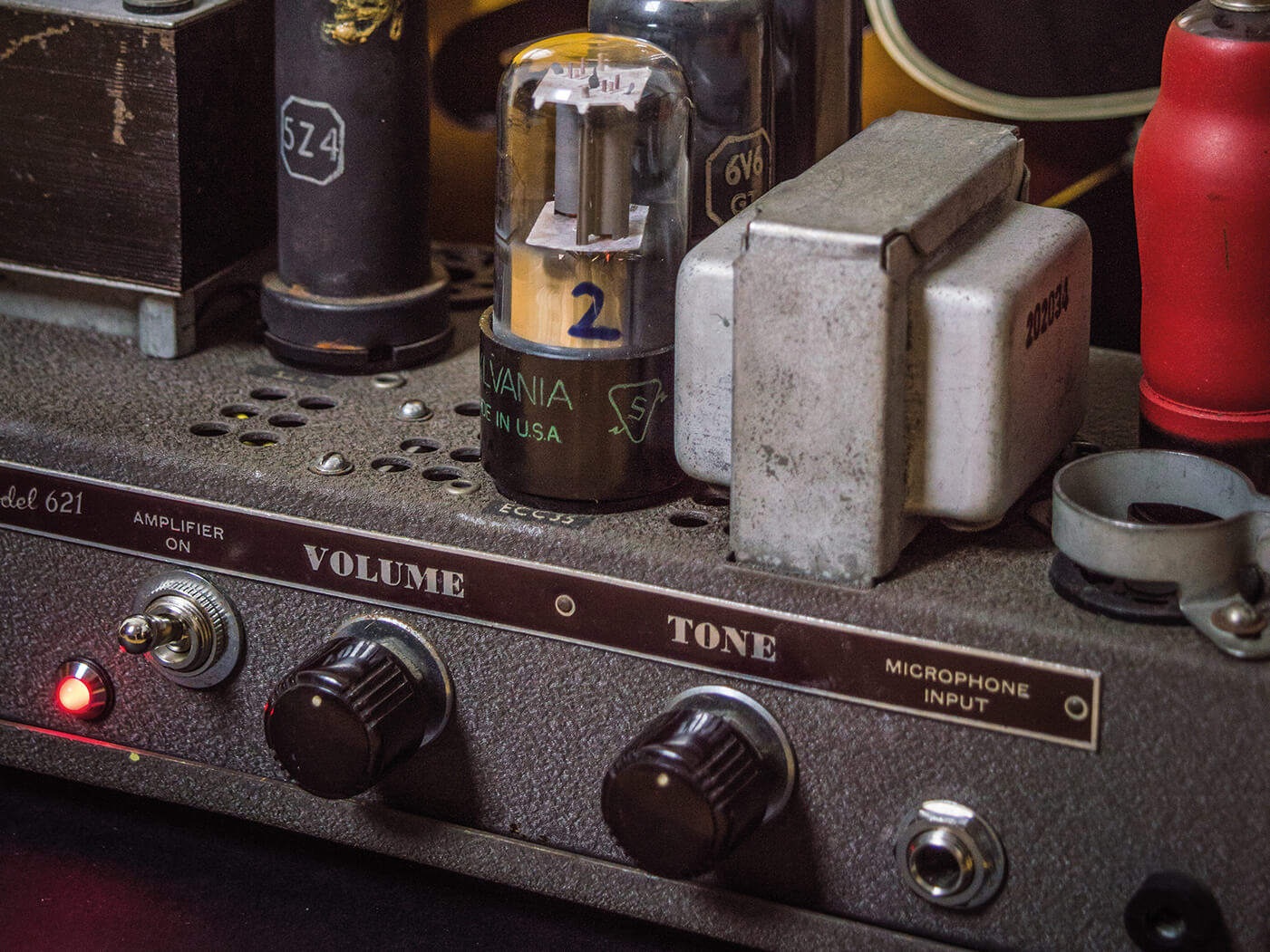
We return to our Filmosound projector amplifier-conversion project for a third instalment – and things suddenly take an unexpected twist…
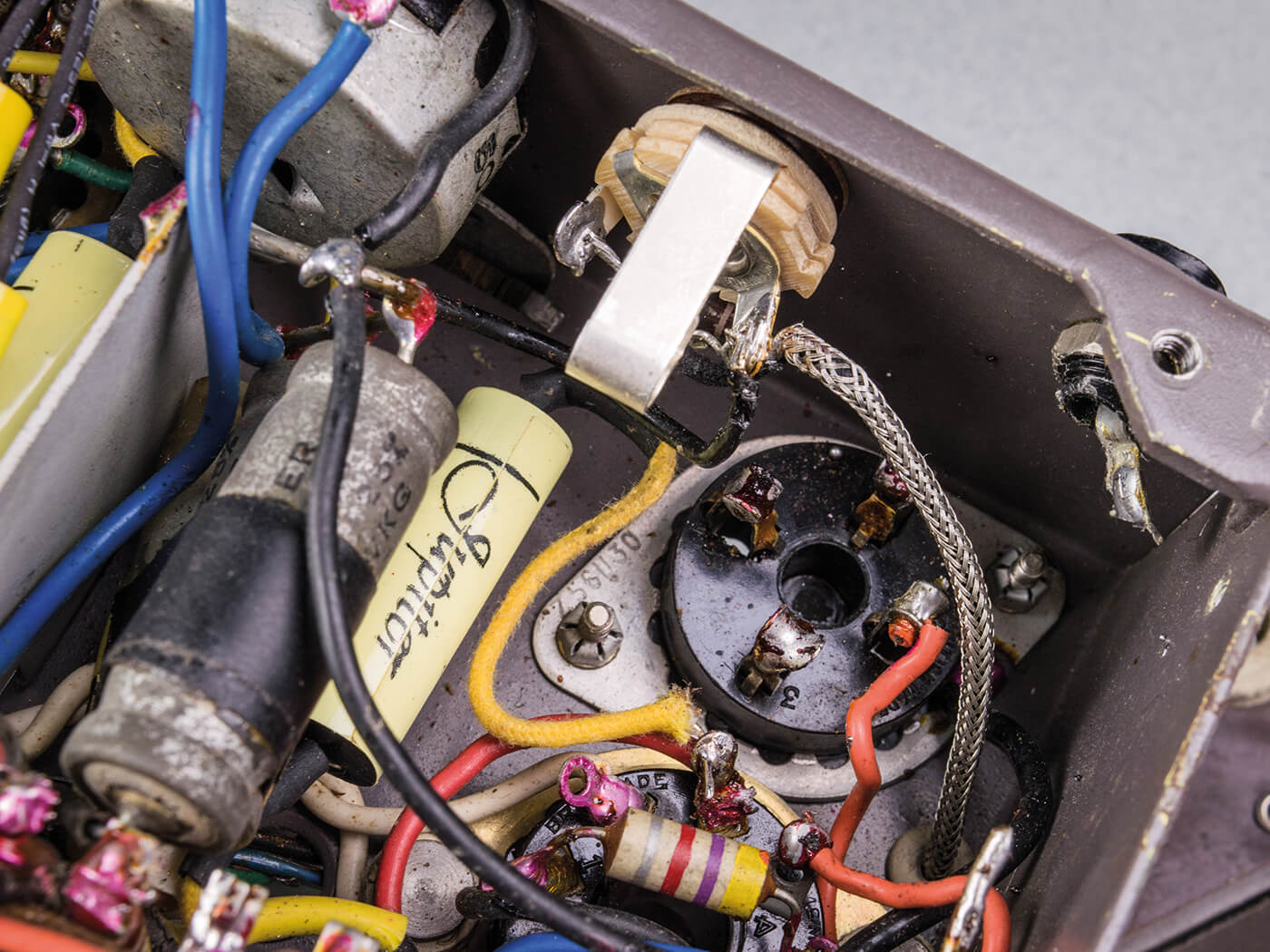
Last time, I signed off with my Filmosound working and passing signal, but also squealing and producing a lot of unwanted noise. Having done some research, it transpires this is a known issue with Filmosound conversions, because the green signal-carrying grid wire emerges from the chassis and plugs onto the top of the EF37A pentode.
With the amp bolted into a metal projector chassis, the cable would effectively have been shielded. However, the standalone arrangement allows the wire to pick up interference and send it straight down the audio path to be amplified along with the guitar signal.
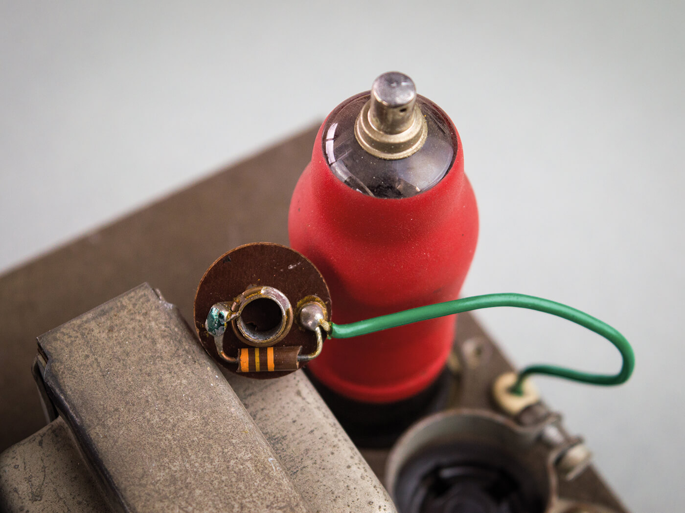
A couple of weeks prior to getting back into this project, I received an email from Tony Teixeira of Tex Amps asking how the conversion was coming along. I explained the noise issues and he said that I should remove the green wire connected to the EF37A grid and replace it with a shielded cable. He also suggested replacing the 33K resistor on the grid connector with a 47R resistor.
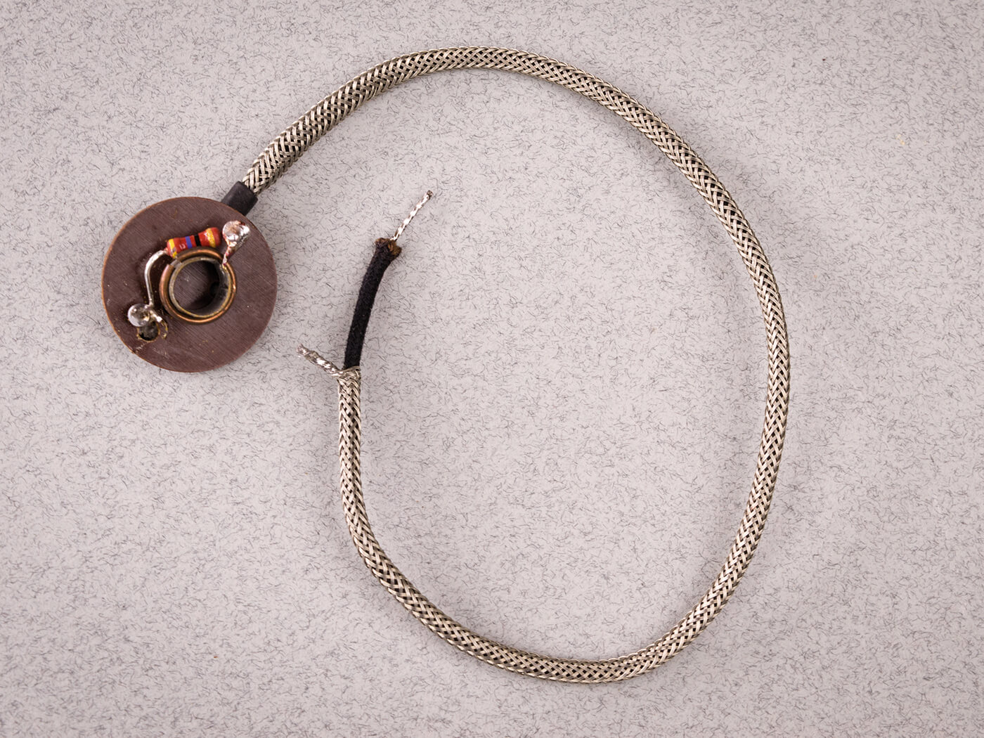
Tony’s instructions are followed to the letter, but results are mixed. The amp is still noisy and the squeal sets in at the same volume level as before, but there is a dramatic improvement in sound quality. Before, it sounded clean and a little dull, but now I get my first taste of how the stock Filmosound circuit overdrives and it’s pretty exciting.
Still, I notice that the amplifier produces next-to-no noise when the volume control is turned down, so I figure it’s time to tidy things up around the input section of the amp.
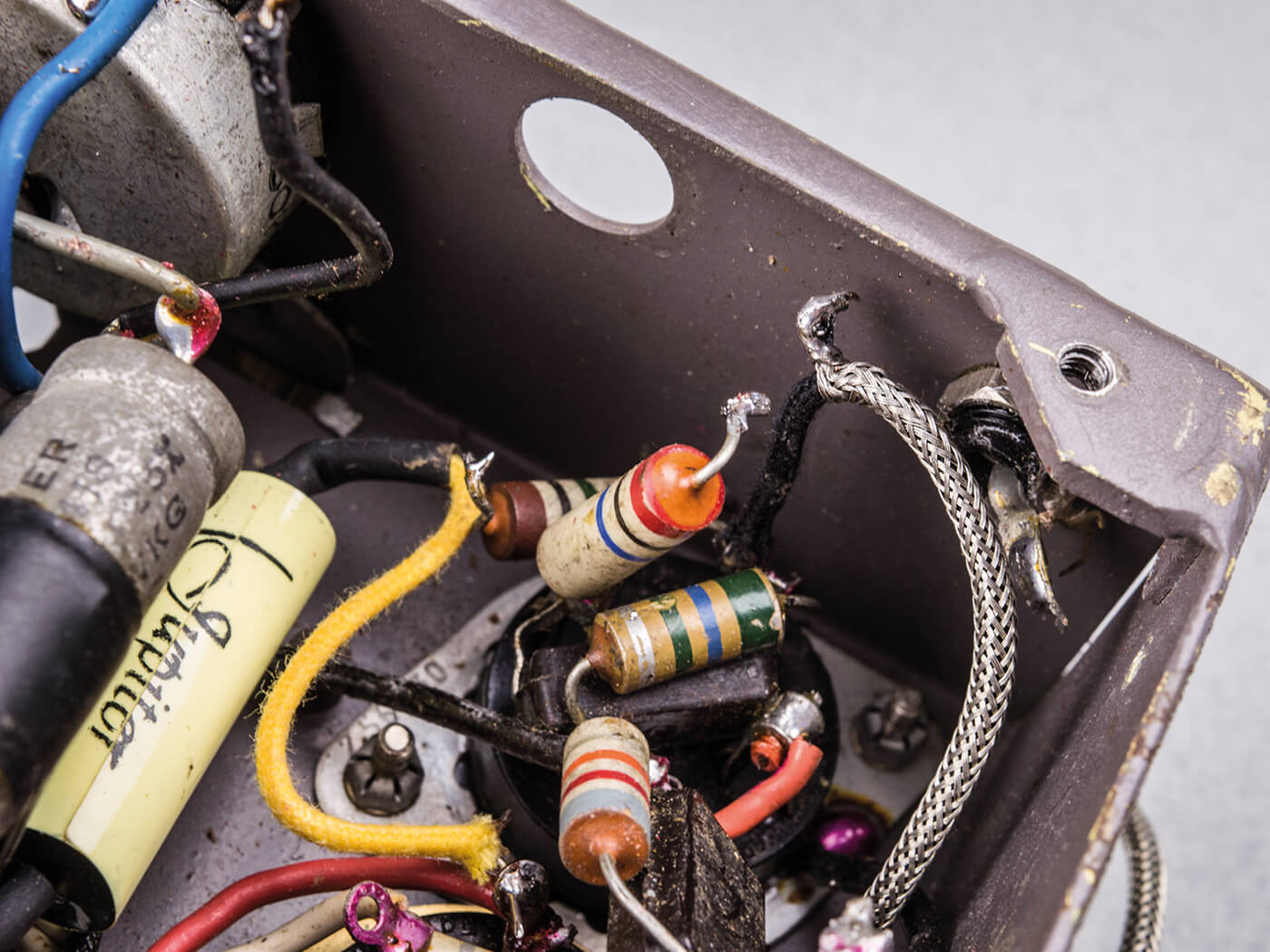
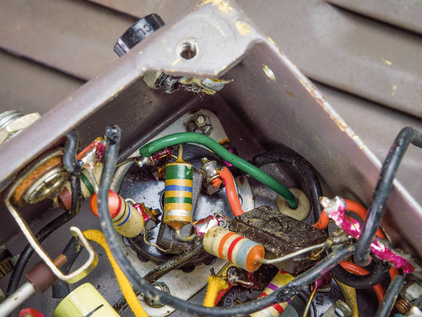
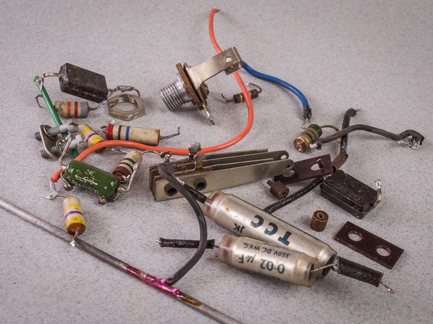
Checking the schematic, I notice a bunch of peculiar wiring around the jack socket. Since this is, after all, a projector amplifier, I can’t claim to understand everything that’s going on inside this circuit, but some of the dense cluster of resistors seem to be related to the projector-lamp circuit.
There’s also a mechanical linkage going from the tip connector of the input jack to a switch in the oscillator section of the amp. Because that is now redundant, I decide to remove the mechanical parts and all the resistors that appear unnecessary.
I also install a modern amplifier input jack with a switch tag that connects the tip to ground when nothing is plugged in. A 1M resistor is soldered between the tip and sleeve connections in the usual way, with one resistor leg linking the sleeve and switch tags. I can now solder the shielded grid wire directly onto the jack socket and it’s time to test the amp again.
Sounds alive
What comes next is a bit of a shock – but thankfully, not the potentially fatal electric kind. The Filmosound is impressively quiet until I hit a chord and get one of the most harmonically loaded overdrive tones I’ve ever heard. It’s also very well defined and quite punchy. If this is what Filmosounds are all about, no wonder they’re so well regarded –
I can understand why some restorers prefer to retain elements of the original circuit.
In contrast to tweeds, the tone control isn’t simply a treble roll-off. Things get a bit brighter as it’s turned clockwise, but I also hear the bass response shifting – with bass rolling off as things get brighter and the tone getting fatter rather than duller as the tone control is turned anticlockwise. I’d anticipated disappointment with the stock circuit and was resigned to gutting the whole amp and building something from scratch. However, I’m so impressed with what I’ve heard so far that, rather than rebuild, the plan is now to optimise the existing circuit with some basic maintenance and minor modifications.
Taking precautions
So far, I’ve been riding my luck, because getting the amp up and running was so easy. But I now need to check that everything is running close to spec. Unlike Fenders, Marshalls and all the other classic amps, tracking down a Filmosound 621 schematic isn’t easy. Eventually, I found one here.
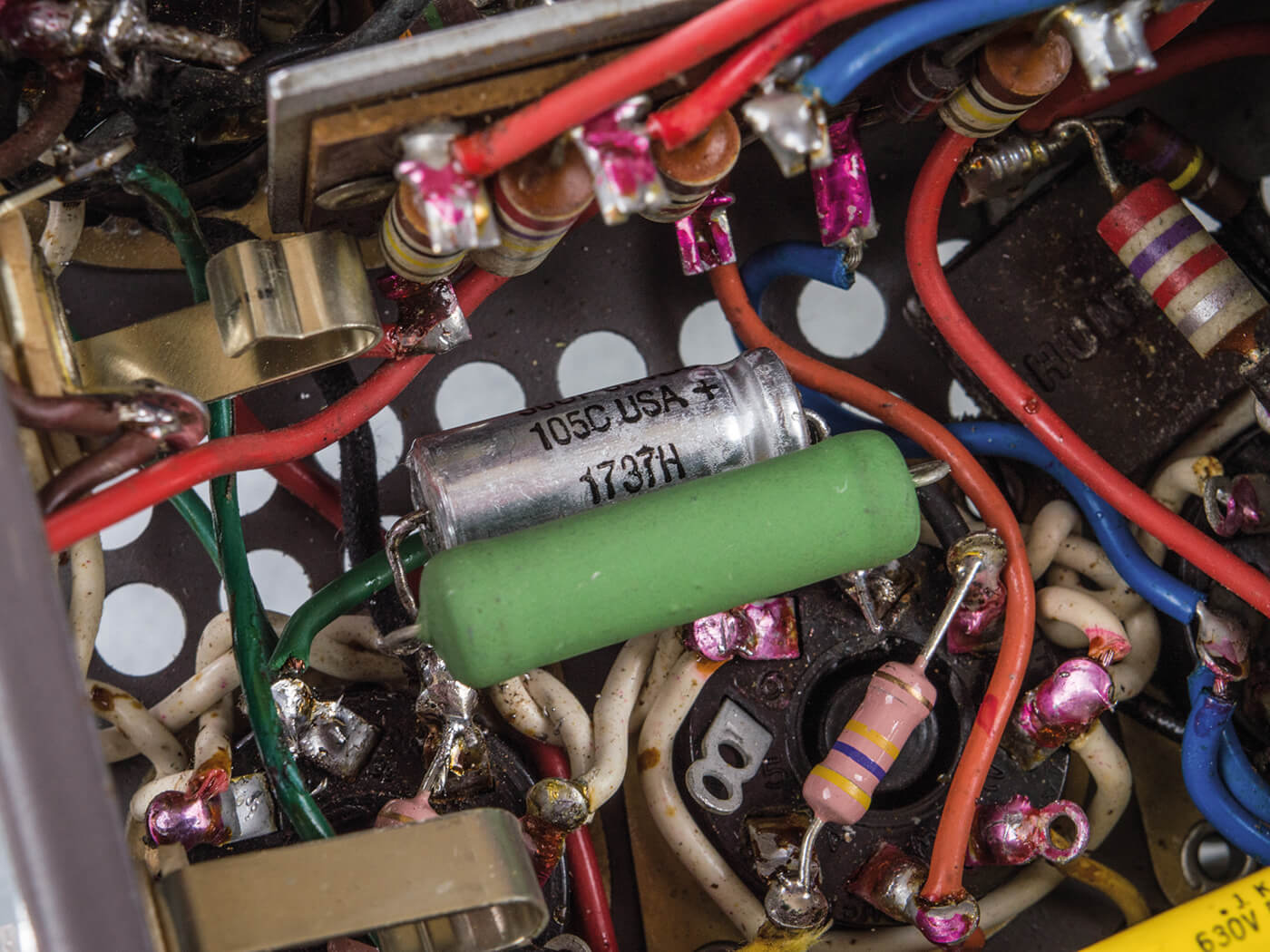
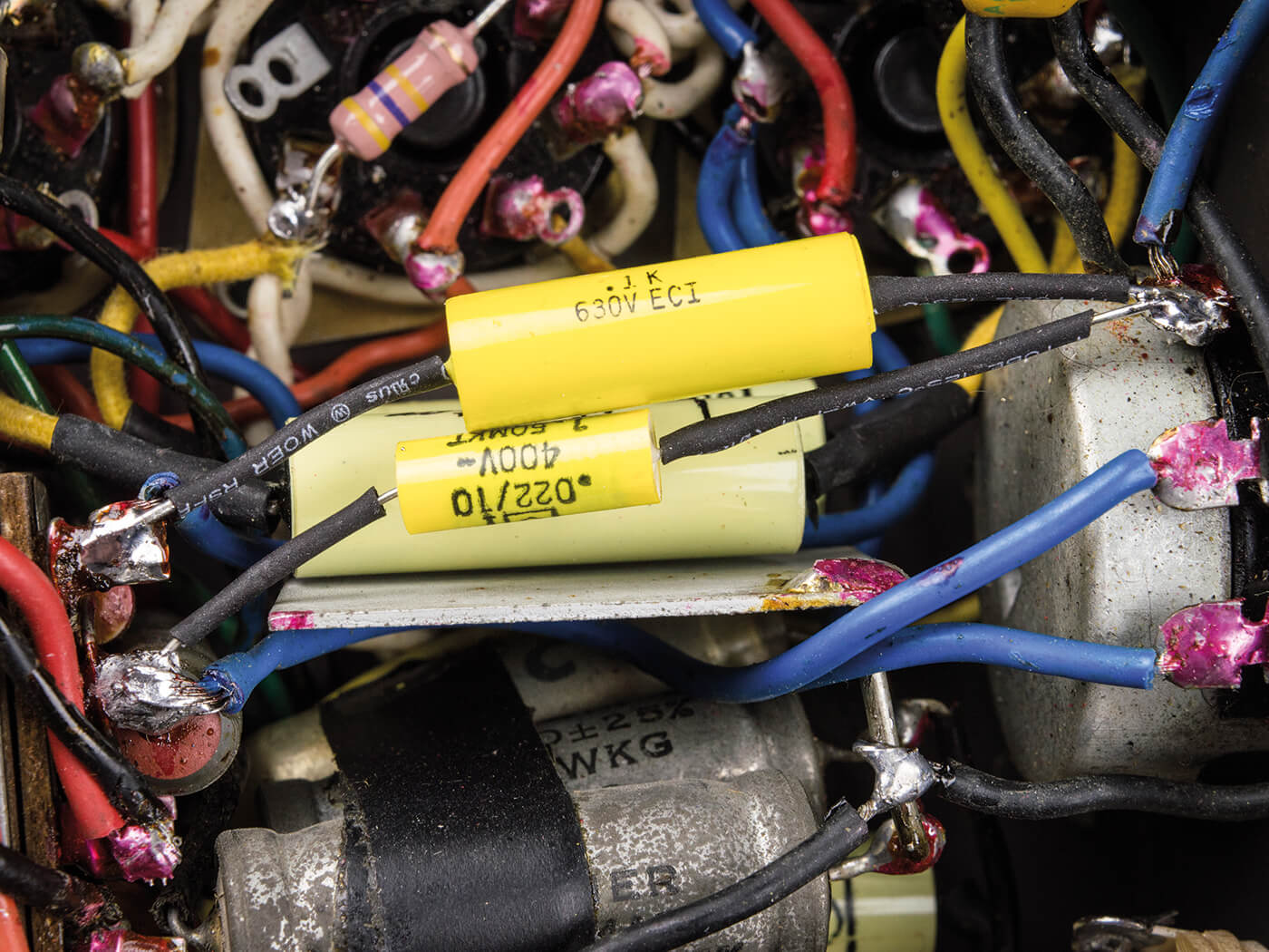
Many of the component values are hard to read, but at least it gives me some voltage test points and I’m able to establish that my amp is in pretty good shape. Even so, there are some things I must do to keep it that way, and swapping out the cathode-bias capacitor on the 6V6s is first on the list.
I decide to leave the existing, and frankly inaccessible, 50uF capacitor in situ and make a slight wiring alteration so a modern replacement can be situated next to the bias resistor. Electrolytic capacitors can leak and drift in value, so it’s a sensible precaution. With that done, I can check the bias of the 6V6s.
Biased view
Although this is a cathode-biased amp, cathode-bias resistors can drift in value and the mains voltages coming out of our wall sockets may differ from the 1950s. Therefore, it’s essential to check those valuable power valves are running safely. To measure bias,
I use a method based on the resistance of the output transformer’s primary windings.
If you look at the schematic for any push-pull amp with two power valves, you’ll see that the primary side of the output transformer has three connections – with two going to the valve plates, and the ‘centre tap’ wire going to the power supply. By measuring the resistance between the centre tap connection and the plate connections, Ohm’s law can be used to calculate the current draw and plate dissipation of each valve.
As with all things related to valve electronics, this is potentially dangerous and you need to observe safety protocols. When making multimeter connections, it is absolutely essential that the amp is disconnected from the mains and that all residual voltages within the amp have been drained off.
With the multimeter test probes clipped onto the rectifier tag that connects to the transformer centre tap and the front 6V6’s plate (pin 3), I measure resistance between them. I do the same with the other 6V6 and the readings are 240R and 221R. Leaving the test probes in situ, I set the multimeter to read DC voltage and measure the voltage
drop across the transformer winding.
The amp is switched off, voltages are drained and I clip the multimeter probe to the plate of the other 6V6. The amp is switched back on and I now have voltage-drop readings of 10.1V and 9V. Since current (I) equals voltage (V) divided by resistance (R), I can deduce that the front and rear 6V6s are drawing 42mA and 40.7mA respectively.
After switching off and draining again, I clip one test probe to chassis ground and leave the other on the valve plate to measure plate voltage. I do the same for the other valve and get 343V on each. Multiplying the plate voltages by the current reading in milliamps gives me plate-dissipation results of 14.4W and 13.9W with the stock 250R cathode-bias resistor.
For cathode-biased 6V6, I’m shooting for 12 watts, or just below, so the 6V6s are running way too hot. After a bit of experimentation, I settle on a 340R cathode resistor. This gives me a plate voltage of 352.5 and voltage drops of 8.2V and 7.2V. Crunching the numbers, I get plate dissipation readings of 12W and 11.5W, and I’m calling that ‘close enough for jazz’.
Zone on tone
The tone circuit is connected to the first cathode of the ECC35 double triode as well as the negative-feedback loop. I had anticipated disconnecting the negative feedback to liven things up, but that renders the tone control inoperative and without negative feedback,
the Filmosound sounds a bit overcooked.
Even so, I suspect the control range is somewhat restricted. Knowing how capacitor values tend to drift over the decades, I decide to swap out the tone-circuit capacitors to be sure everything is operating as intended. This greatly improves the tone control’s functionality and I hear a very clear treble boost/bass roll-off at one extreme, with treble cut and bass boost at the other. In contrast to early Fender tweeds with lone tone controls, the Filmosound control’s default position is around the centre rather than near maximum.
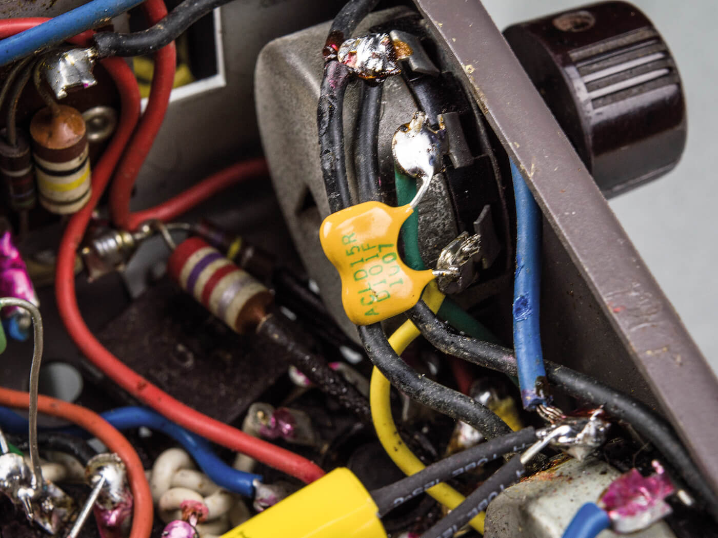
At lower volume settings, I still feel I’m missing some sparkle frequencies and I have a simple solution for that. I’m a big fan of treble-bleed capacitors, because they allow you to extend an amp’s upper-frequency response in a non-intrusive and completely reversible way. Fender used them in several amp models, often with an accompanying bright switch.
Bright capacitor values can range from 50pF to 500pF and they are wired across the input and output tags of the volume potentiometer. The smaller the capacitor, the higher and narrower the frequency range. Larger caps will extend the ‘treble bleed’ down to the upper mids and midrange. When the volume control is turned down, high frequencies can ‘jump’ across the pot unhindered and this keeps everything bright and clear.
When the volume control is turned up, the resistance between the pot’s input and output drops, so the cap’s influence decreases. At maximum volume, the cap has no effect at all.
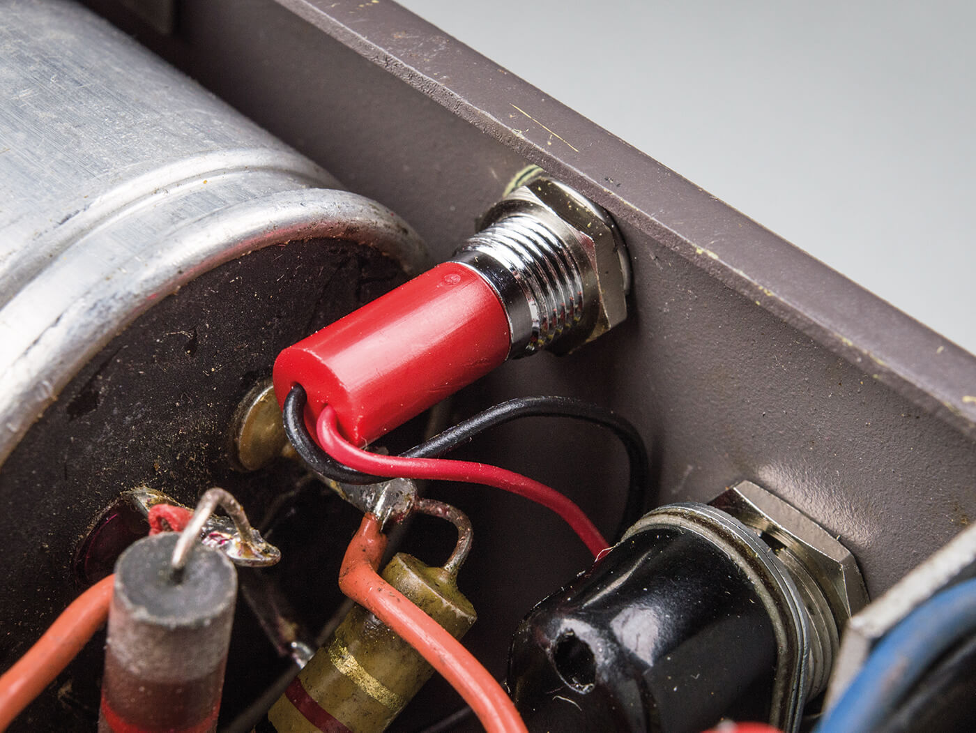
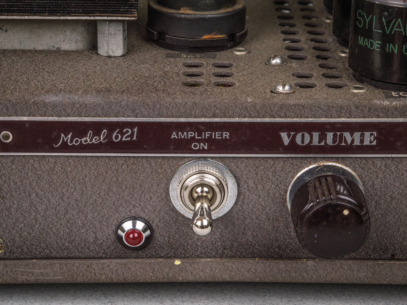
I use silver mica capacitors for this application and it’s fun to experiment to find the value that works best for your pickups and sonic tastes. For this Filmosound, I go with 120pF. All that’s left is to drill a hole in the front of the chassis, near the power switch, where I just about manage to squeeze in a pilot light.
Filmosounds good
You may be wondering why I haven’t replaced the multi-section filter capacitor in the power supply – given that I invariably advise doing so with vintage amps. Well, firstly the amp runs with no discernible power supply hum, so the capacitors inside the canister are all clearly doing their jobs. Secondly, I am familiar with this brand from Leak hi-fi amps, and my pair of TL/12 Plus monoblocks from 1963 are still running silently with their original filter caps. There’s a distinct possibility that I got lucky with this amp because, had it been ‘dead on arrival’, I certainly wouldn’t have relished the prospect of debugging it.
I’m not surprised that most of the techs that work on Filmosounds simply gut the insides, but it’s a shame, because the stock circuit sounds so good that none of the mods I had planned now seem worthwhile.
The tone circuit is particularly interesting, because it behaves more like a girth control that can push the low mids or roll off bass to enhance tightness and brightness. In contrast to tweeds, rather than adding gain at its brightest, overdrive increases when the tone control is rolled back to push the lows.
The Filmosound combines the chewy fatness of early 50s Fender tweeds and the extra gain and aggression of late-50s tweeds, with tighter lows and the smoother overdrive of a Gibson GA-40. It always sounds clear and larger than life, and the way overdrive responds to playing dynamics is resolutely old school. I find the clean and edge of breakup tones this amp produces just as exciting as its proto-metal overdrive. Those professionals who restore and convert these amps stress the quality of the transformers, and I can certainly see why.
Most seem to run Filmosounds with 5Y3 rectifiers, but I prefer the stock 5Z4. It provides a soft startup and the HT is higher. As a result, the amp has livelier dynamics, and a bit more clean headroom and clarity. But be careful, because metal-cased valves can get dangerously hot and the bias-resistor value may need to be changed along with the rectifier if you want to experiment.
The premise behind this project was to find out if it’s possible to get outstanding 1950s amp tone for less than £200. The clear and unequivocal answer is yes, and in this case, £180 would be closer to the mark. All that remains is to pick the ideal speaker and decide whether to use the Filmosound as a standalone head, or build a combo cabinet for it. Watch this space, because there’s every likelihood you’ll be seeing this amp again in the not-too-distant future.
Check out the other parts of this DIY project here.