Related Tags
DIY Workshop: Jazzmaster Bridge & Wiring Upgrades
Most Jazzmaster lovers will concede that the classic stock bridge is something of a bête noire when used with modern strings. We tackle the installation of a Mastery unit and show you how to wire up your controls to keep hum to a minimum.
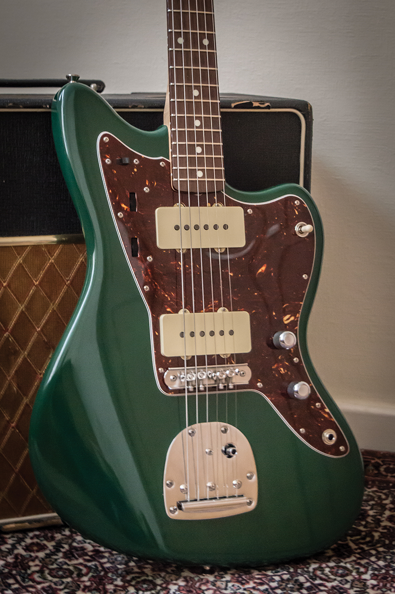
Jazzmasters are nothing if not eccentric beasts, and that presents certain unique challenges if you want to mod, repair or restore one of your own. The most common worry for those of us tackling Jazzmaster restorations and repairs is the bridge, but it doesn’t have to be. Don’t worry if you have no interest in Jazzmasters and their potentially troublesome hardware, either – you’ll find this advice applicable to Jaguars and Bigsby-equipped Teles, too.
The other issue that often plagues Jazzmasters, and single-coil guitars in general, is hum – so we’re also going to look at how to shield your internals to keep the noise down, and also how to wire up the controls themselves.
Mastering The Bridge
In 1958, Fender began using threaded saddles on some of their guitars – Telecasters got them, along with the new Jazzmaster model. The idea behind this was that the multi-grooved design would allow players to set their own string spacing – and with a nice steep break angle over the saddle they work well enough. However, the Jazzmaster’s break angle is slightly too shallow, and the grooves on the saddles are not deep enough to prevent strings from jumping out.
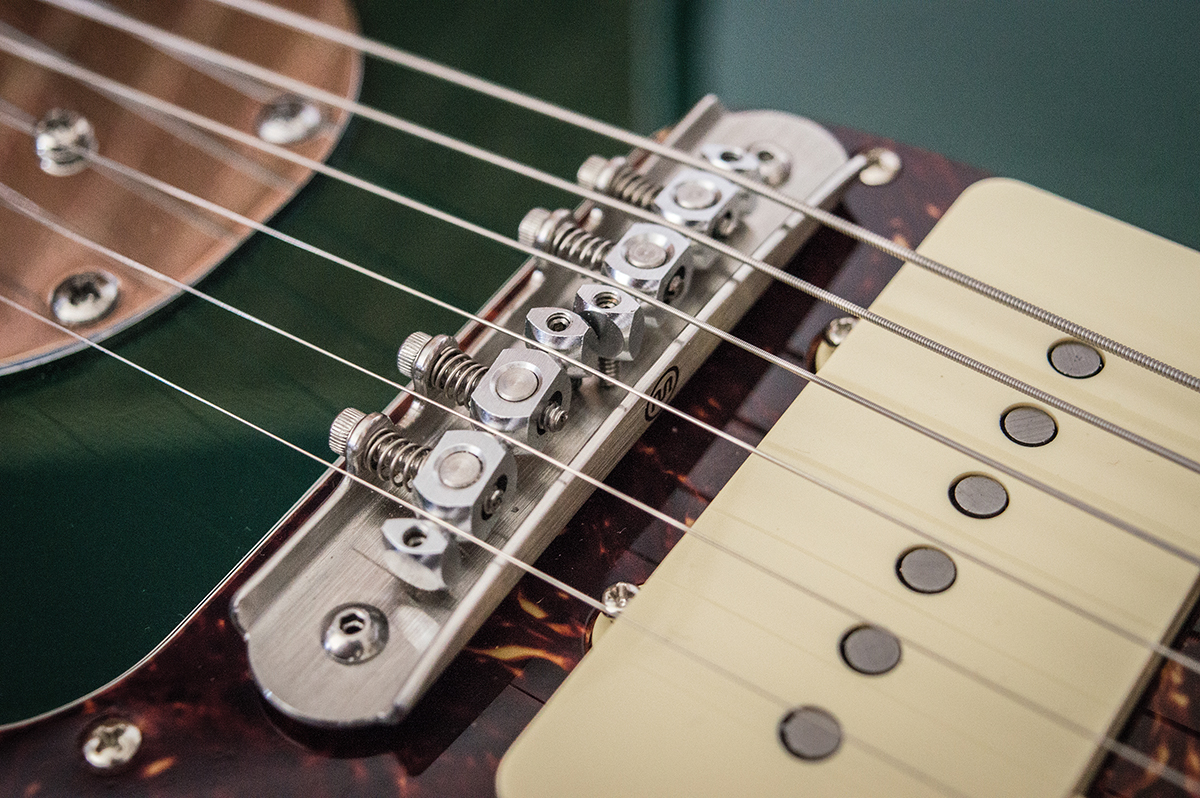
Mastery’s bridge design features swivelling low friction saddles, global height adjustment, radius setting and a cutaway back plate for clear string path
This wouldn’t have been an issue for jazz players with heavy flatwound strings, which as the name suggests were the target audience for the Jazzmaster. However, it never really caught on with jazzers, and the surfers, garage-rockers and noiseniks who took the instrument to heart have generally had to retro-fit a Mustang bridge as a drop-in replacement. It’s not a perfect one – Jazzmaster and Mustang bridges are known to rattle, and if you don’t get your neck angle right, the strings can buzz against the rear plate of the bridge.
Another well-documented issue involves the action height adjustment screws. Jazzmaster bridges are attached to posts with grub screws at the bottom. The posts are inserted into cups or ‘thimbles’ that are pressed into the body and a long Allen key can be directed through the centre of the post to set the bridge height at each end.
For shielding Allparts UK supplied a Fender aluminium plate and adhesive backed copper foil
In practice the grub screws can be too loose and prolonged vibration and whammy bar action can cause them to retract within the posts. As a consequence, the action becomes lower and strings will begin choking out and even stop ringing altogether.
A popular modern solution is the Mastery Bridge. Designed by luthier John Woodland, this high-end unit is made in Minneapolis and has garnered a stellar reputation with such Jazzmaster heavyweights as Nels Cline, Thurston Moore and Elvis Costello. Bill Frisell uses a Mastery bridge with a Bigsby on a JW Black T-style. Curiously, J Mascis prefers a tune-o-matic.
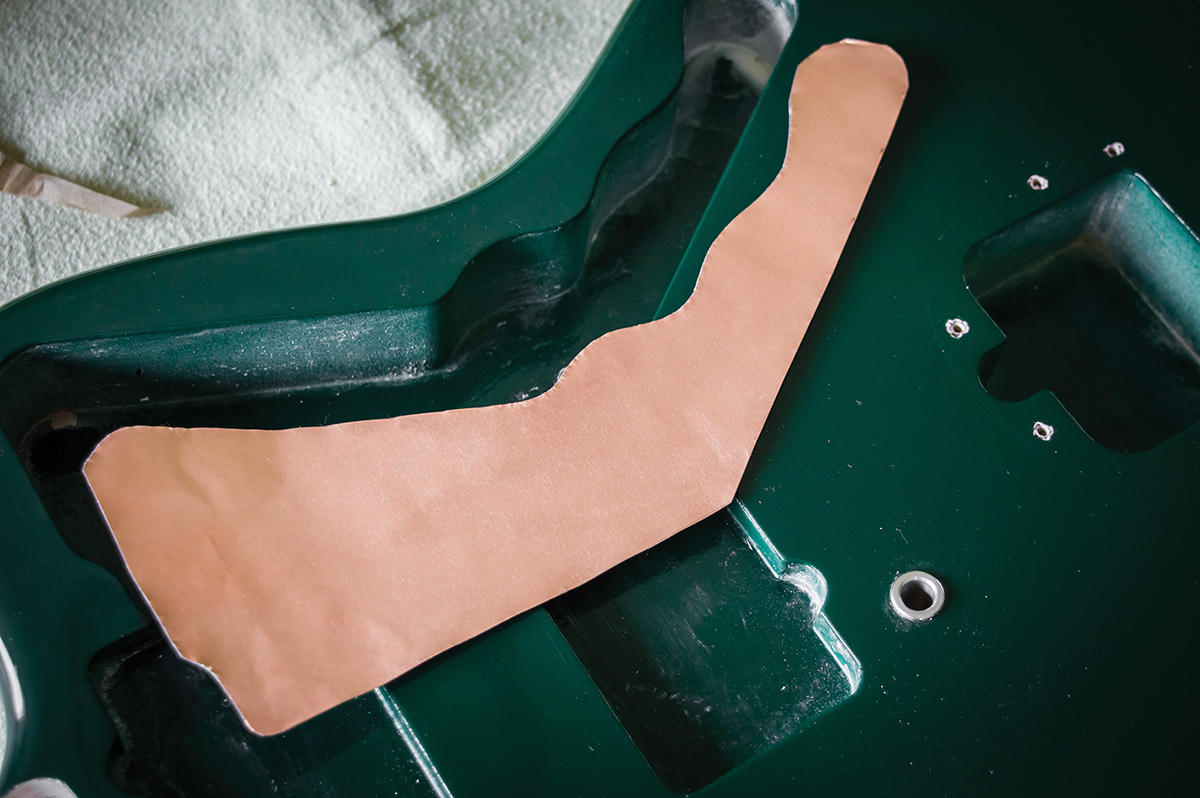
Transfer the cavity shape onto the foil by pressing the edges with your finger then cut them out with scissors
Bridge Fit
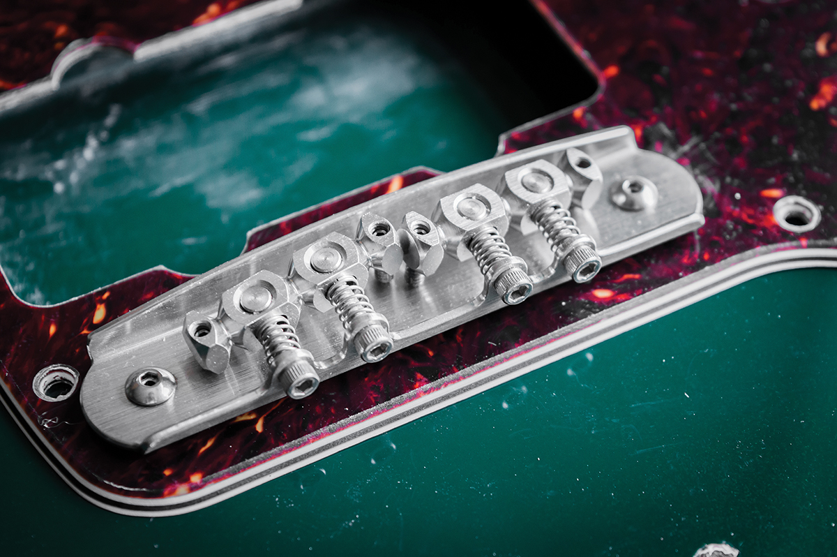
The Mastery unit looks more like a piece of contemporary sculpture than a regular bridge, and it purports to solve every Jazzmaster problem. The bridge features two saddles, each with two pivot points allowing both trios of strings to be intonated accurately. In addition, saddle heights can be set at each end to conform to various fingerboard radiuses. With our guitar’s 9.5-inch radius neck, a 7.25-inch Mustang bridge was never going to be a workable solution without under-saddle shims.
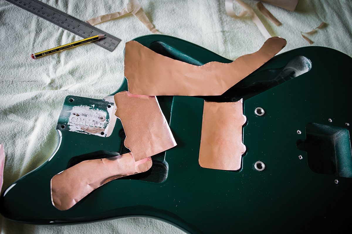
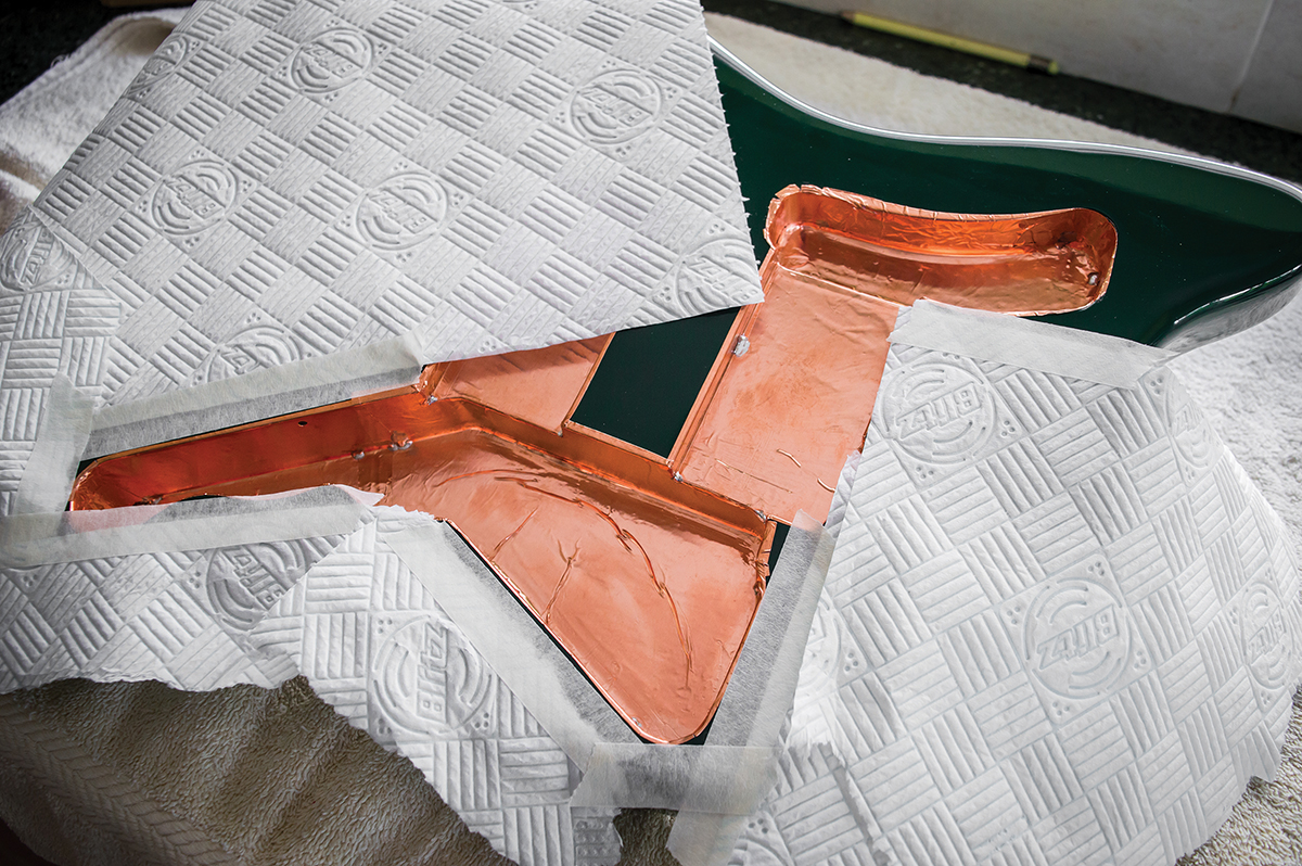
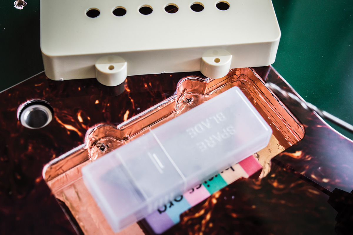
After cutting out the foil to line the bases of all the cavities, we set them to one side
Although you can drop a Mastery bridge into the factory thimbles, you can also use Mastery’s thimbles instead. The Mastery posts and thimbles are made to such fine tolerances that when you press a post into a thimble, it forms a vacuum. Unlike a regular Jazzmaster bridge, which is designed to rock back and forth with the vibrato, Mastery bridges are fixed in place.
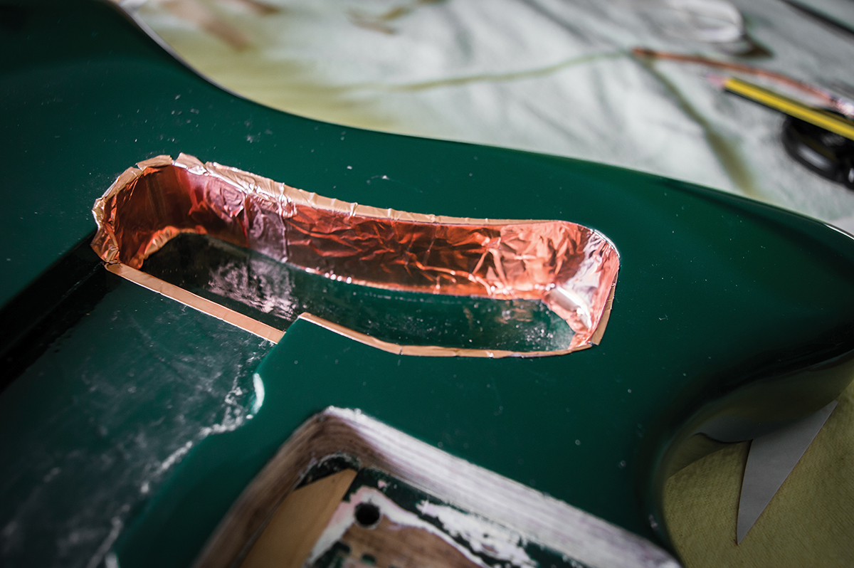
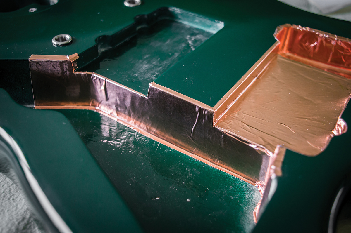
Foil is applied to the sides then lipped over the top and bottom edges
Many Jazzmaster players regard the stock bridge as a cause of tuning instability because it doesn’t always return to position correctly. I decided to install the Mastery thimbles here, however it’s worth noting that Mastery bridge posts do not fit Japanese-made thimbles as tightly. If this is the case with your guitar, you may decide to change the thimbles as well as the bridge. Check the thimbles on the instrument you are upgrading to see what fits best.
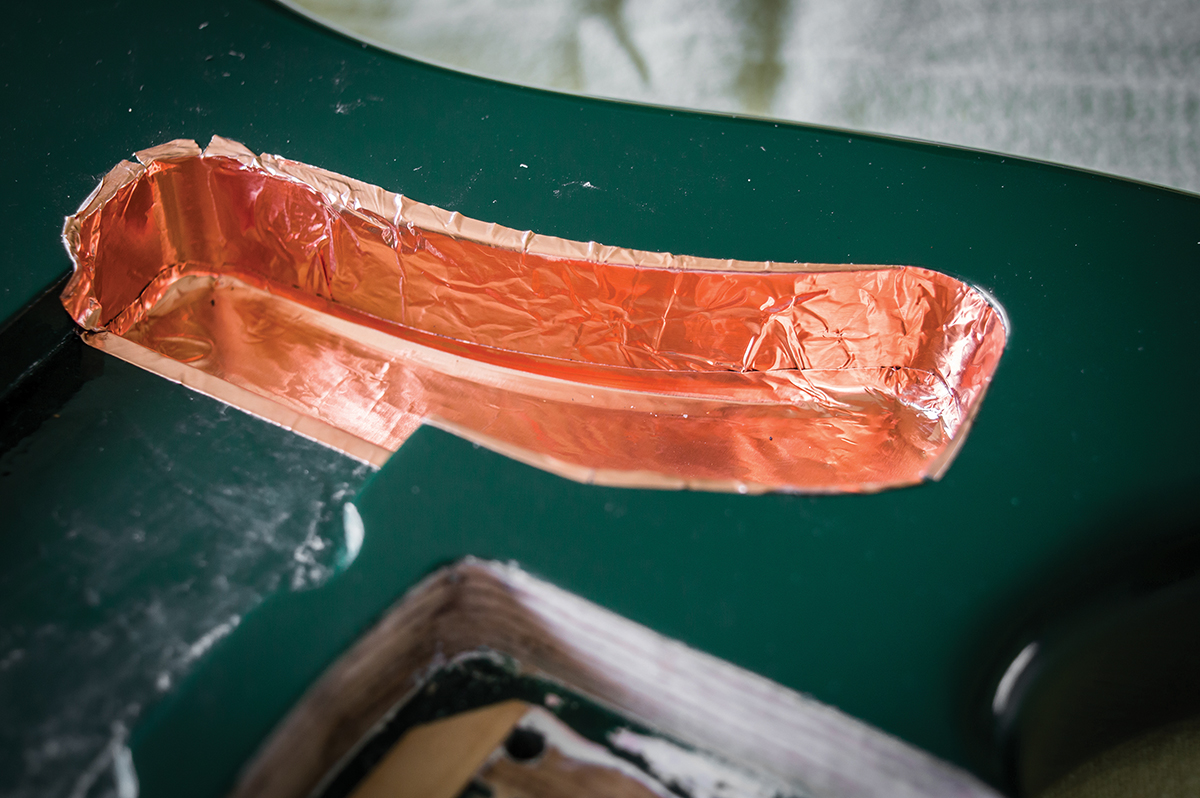
After the sides are done you can lay in the base and the second circuit rout is now completed
The Mastery thimbles also differ in size from Japanese thimbles. The Mastery dimensions are 9.3mm wide and 2.05mm long compared to 8.545mm and 1.95mm. So if you do decide to swap out the thimbles on a Japanese-made Jazzmaster, some re-drilling may be required. I covered the process of installing bridge thimbles in our November 2015 Telecaster revamp feature.
Once I have the thimbles installed, I adjust the post grub screws to extend beyond the posts to ensure they contact the base of the thimbles. The grub screws are also fairly tight, although they do move freely enough for adjustments. Before dropping the bridge in, I very slightly slacken the screws connecting the posts to the bridge base because the Mastery allows you some leeway to compensate for thimble spacing discrepancies.
Next we’re moving on to shielding the main control cavity
The posts went straight into the thimbles, so I re-tightened the base screws and then retracted the post grub screws to lower the bridge height. It was immediately apparent that the neck would need a shim, but the factory saddle settings provided a good starting point for intonation and the acoustic tone displayed superb clarity and sustain.
Raise The Shields
Whether each of the instruments Leo Fender introduced was an improvement on previous models is a matter of debate, however there’s no denying each one represented an evolutionary stage in Fender’s approach to guitar design. The outward differences between the Strat and the Jazzmaster are obvious, but one of Jazzmaster’s groundbreaking features hides under the cover.
Protect the paintwork from stray blobs of solder with kitchen paper
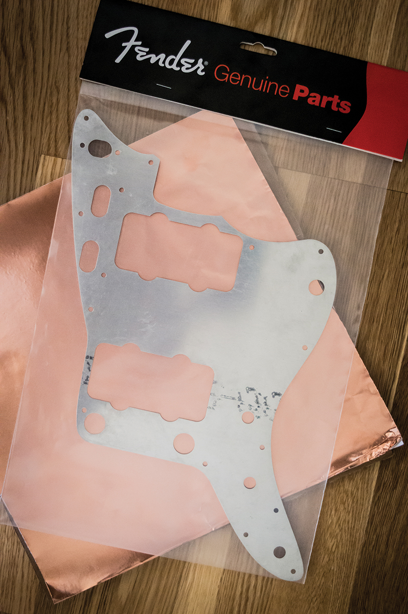
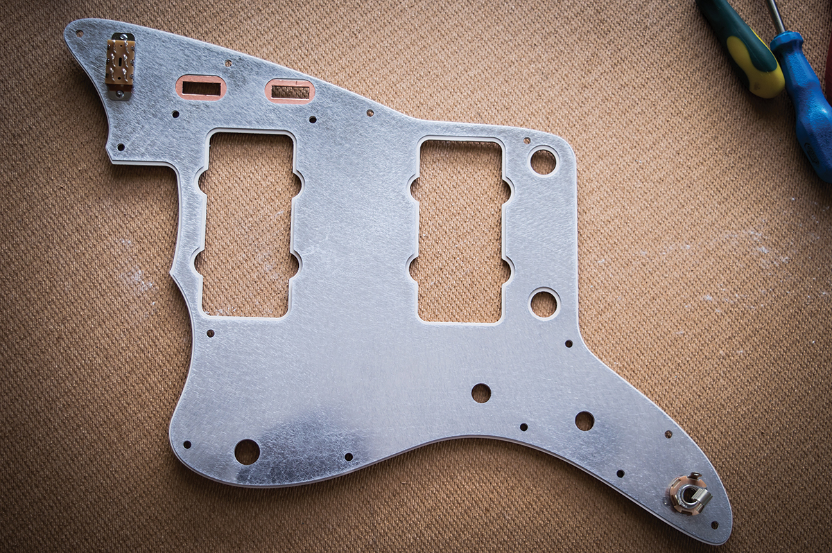
Gibson and Gretsch introduced humbucking pickups in 1957, so Fender must have been considering how to reduce noise without deviating from single-coil pickups. He went down the shielding route and lined the control cavities with form fitting brass. The first Jazzmaster pickguard was aluminium, which also provided shielding, so when Fender changed to a celluloid nitrate guard, he placed a thinner aluminium shield under the pickguard.
Fortunately, you can buy a Fender-branded repro of the aluminium shield, but full cavity shields are impossible to come by. Instead I decide to use sticky backed copper foil to line the body cavities and found the foil and a shield at allparts.uk.com.
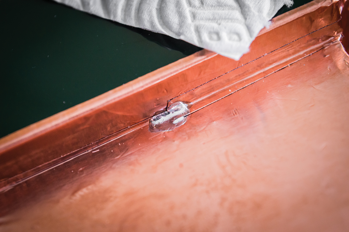
Solder joints ensure electrical continuity across the screening
The process of lining the cavities begins with laying the foil over the cavities – with the backing still on the foil – and pressing around the edges of the routs to transfer the shapes onto the foil. This provides a crisp outline and you can cut out the shapes with a sharp scissors. With foil cutouts made for the bases of the control cavity routs and both pickups, I set them aside while applying foil to the sides of the routs.
I try to leave a slight overlap at the top and bottom so the foil will contact the aluminium shield and make up for any inaccuracies in the base cut outs. Some of the shapes were tricky and I found it easiest to work with shorter strips of foil rather than attempt to complete each area with a single strip. Once the sides are done I lay in the bases and patch up a couple of areas where I can see green paint.
The shield is aligned with the scratchplate and held in position with the switch and jack socket
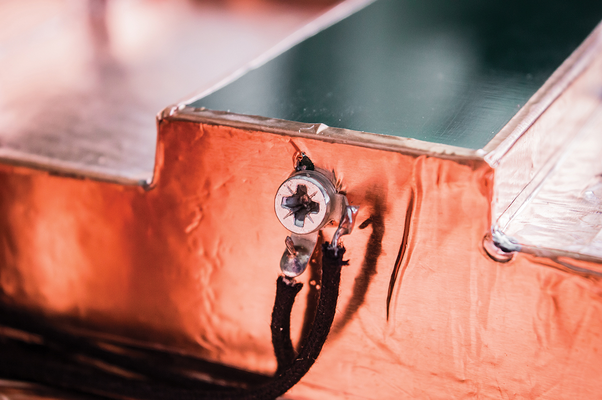
It’s important for there to be electrical connectivity across every section of foil. Wherever I had used multiple strip or added patches, I applied blobs of solder to the joins between the various pieces. I also applied solder to the joins between the foil on the sides and bottoms of the cavities. A multimeter set on ‘continuity’ was used to check that the shield was properly connected up and then it was time to move onto assembling the pickguard.
Packing The Pickguard
I perform a test fit with the shield and the pickguard to establish that everything lines up really well. However there are some oversized holes around the tone circuit switch and controls, so I add some copper foil patches and cut out the holes using a craft knife.
Load hardware with pots facing down to ensure it all fits in the cavities
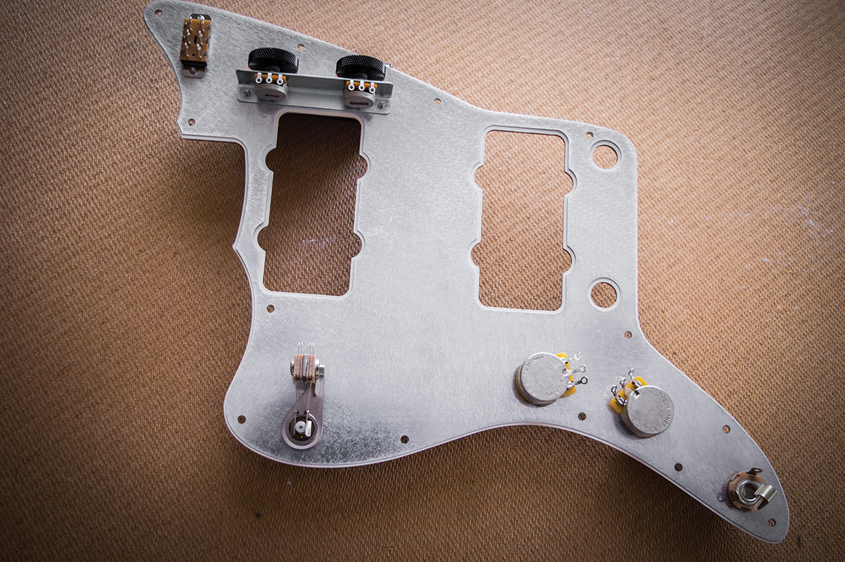
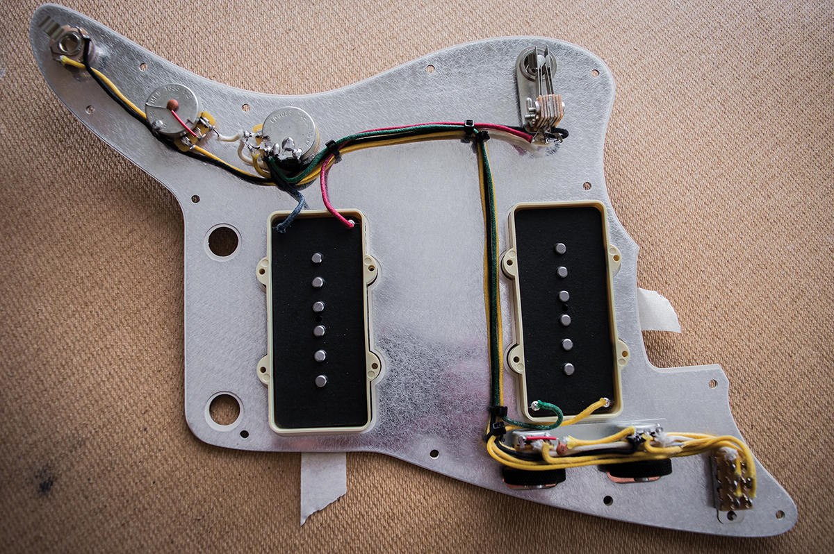
The shield isn’t glued to the guard and instead, the potentiometers and switches clamp it in position. I loosely fit the circuit switch and the output jack, line up all the screw holes then tighten up the screws and nut to hold the shield in place before loading up the pots and pickup selector switch.
The second circuit volume and tone pots are mounted on an ‘L’ plate so they’re at 90 degrees to the pickguard. They’re solid shaft 16mm pots rather than the full-sized 22mm split shaft pots and Allparts UK provided the roller wheels, as well as the pots. Each pot comes with a washer and a nut and I find it necessary to install the washers behind the ‘L’ bracket in order to centralise the roller wheels in their slots.
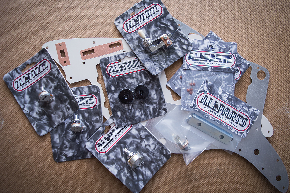
The Allparts Jazzmaster wiring kit provides everything you need for this fairly complex wiring job
You also have to mount the pots onto the bracket and loosely fit the rollers before screwing the bracket onto the pickguard. Once it’s fixed, you can fine-tune the position of the rollers on the pot shafts and tighten the grub screws to fix the wheels in position. Also note that the main volume and tone pots have to be twisted away from the edges to fit because there’s not much wriggle room in the control cavities.
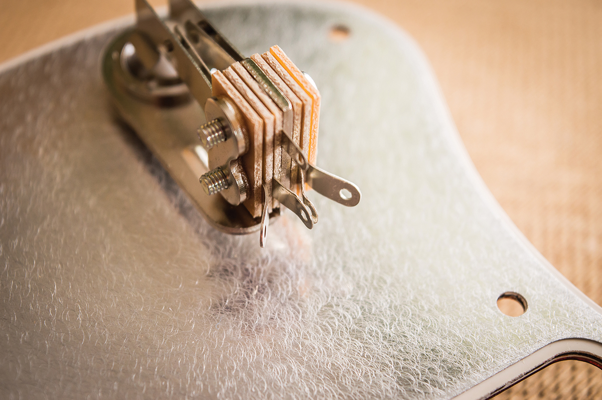
The pickup selector switch’s solder tags must be splayed before you start soldering to prevent shorting out
I ploughed through a bunch of different Jazzmaster wiring diagrams online until I found one I trusted at Rothstein Guitars (www.guitar-mod.com). Most of those I found seemed to show alternative wiring schemes, so be careful. It’s also interesting to discover that the Jazzmaster circuit has a 1meg linear pot for volume and a 1meg audio pot for tone.
The first stage of the wiring is complete – don’t forget to insulate the legs of the tone capacitors
To wire a Jazzmaster, you need to assemble quite a collection of parts. Allparts UK sells a complete Jazzmaster wiring kit, which comes with helpful diagrams. However take care when unwrapping the components, because the shrink-wrap is hard to remove and you may damage delicate switch and pot solder tags if you’re not careful and patient.
We shim up the pickup covers so they’re aligned with the pickguard cutouts then drill pilot holes for the cover screws
In Suspense
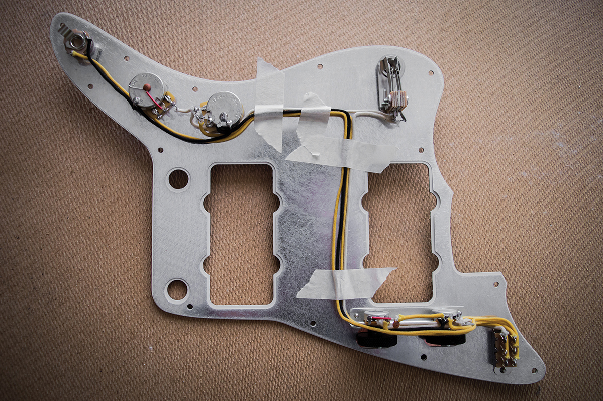
Hooking up begins with grounding the volume pot tag and splaying the solder tags on the pickup selector. While referring to a schematic and photos of Jazzmaster wiring, I connect up the main control pots and the three-way switch.
The fiddliest part is connecting up the pots and switch on the second circuit then running all the longer wires between the two circuits. I use strips of masking tape to hold all the wires neatly in place as I work my way through the installation.
With the wiring finally completed, the wires are held in place using nylon cable ties
You may have noticed that the pickups still haven’t been installed. Unlike Stratocasters, where the pickups are suspended from a pickguard assembly, which can be lifted out in its entirety, Jazzmaster pickups are screwed directly onto the body. To position the pickups properly, I first fit the loaded pickguard onto the body and screw it down.
The pickup covers are then placed into the cutouts with spacers underneath so the sides line up properly with the closely cut pickguard openings, and I drill pilot holes for the cover screws using the screw holes in the covers to guide the drill bit.
The solder tags connect the bridge ground wire to the shield and the shield to the negative terminal of the output jack
Applying masking tape to the top of the covers, I position them inside the pickup openings with the tape holding them in place. The pickguard is then flipped and the pickups dropped into their covers then soldered into the circuit. Once that’s done I do a visual check and test the switches using a multimeter – everything’s good, so I replaced the masking tape with nylon cable ties.
The shielding has to be grounded, so I attach a couple of solder tags to the side of the control cavity with a self-tapping screw. The tags are used for the ground wires connected to the bridge and the output jack. Before screwing the pickguard back down and stringing up, I verified the controls were working properly and was relieved to find I’d done it right first time. If it’s your first time working on a Jazzmaster, you’ll notice that it’s much more complicated than most other Fender solidbodies.
It’s worth the perspiration though, as a few well-chosen upgrades can make all the difference. Happily, the Mastery bridge is everything it’s cracked up to be. First impressions of the Mojo 58-64 pickups I used are also highly encouraging – visit www.mojopickups.co.uk to check out the full range.