Related Tags
DIY Workshop: Rift Amp Modifications Part Two
In the second instalment of our Rift project, we get deeply tweedy with cathode-bias switching, negative feedback modifications and more.
The Princeton Reverb is arguably the most modded of all the classic amplifier designs. In fact, the very first Mesa/Boogies were basically Princeton Reverbs that Randall Smith hot-rodded back in 1969. Since then, all manner of things have been done to this circuit, mostly in an attempt to increase gain and sustain or raise clean headroom and power levels. Various approaches have been taken and some, such as the ‘Paul C’ and ‘Stokes’ mods, have become very well known.
My feeling is that if you want more clean headroom and volume, you’re probably better off installing a beefier Deluxe Reverb-spec output transformer or, better still, buying a Deluxe Reverb. From the get-go, the purpose of this project has been to explore the full potential of the stock circuit without losing its essential character.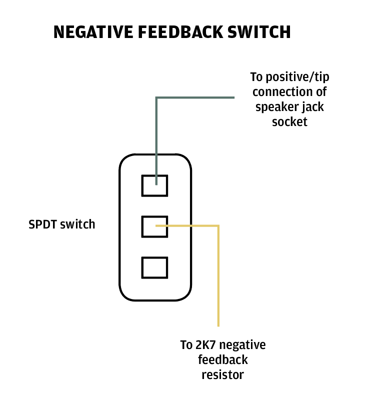
A simple feedback on/off switch is one of the easiest mods you can perform on a Princeton
When I suggested to Chris Fantana of Rift Amplification that the Princeton Reverb could potentially be three amps in one, he thought about it for a few moments and said, “More like five”. So following on from the brownface/blackface tonestack switching and the reverb tweaks we explored in our previous workshop, this month we’ll be attempting to take things in a tweedier direction with cathode-bias switching, negative feedback tweaks and more besides.
Negative feedback fun
Most of Fender’s low- and mid-power tweed amps were designed without a negative feedback loop. The 5F11 Vibrolux that so closely resembles the brownface Princeton is an exception, but negative feedback was never used in any of the tweed Deluxe models.
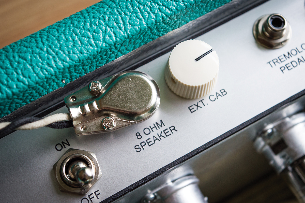
You can replace the external speaker output with a switch or a feedback control, as we have done here
The negative feedback that your boss might give you during your annual appraisal and negative feedback in an amplifier are different things, but the results can be similar. Negative feedback can leave you and your amp feeling a bit flat and somewhat lifeless.
In an amplifier, a connection is made from the positive terminal of the output transformer and a portion of the output signal is fed back to the cathode of one of the preamp valves. Since the output signal will be out of phase with the preamp signal at that point, there will be some phase cancellation that slightly reduces output but makes the amp run cleaner and tightens the bass.
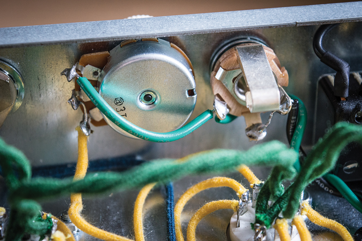
We used a matching feedback control knob; using existing and unwanted holes is easier than drilling new ones
Removing or modifying the negative feedback is one of the easiest mods you can make to an amplifier, and the best thing is that it generally costs nothing and is easily reversed.
Start by de-soldering the green wire from the positive terminal of the external speaker jack and covering the exposed wire with some insulation tape to prevent it from shorting out.
Have a listen and see if you like the tone without negative feedback. If you don’t, simply re-solder the green wire to the external speaker socket and skip to the next mod.
If you decide you like it, but you want to retain the option, you should consider a negative feedback switch. Replacing one of the control pots with a push/pull or push/push pot would allow you to switch the negative feedback from the front panel.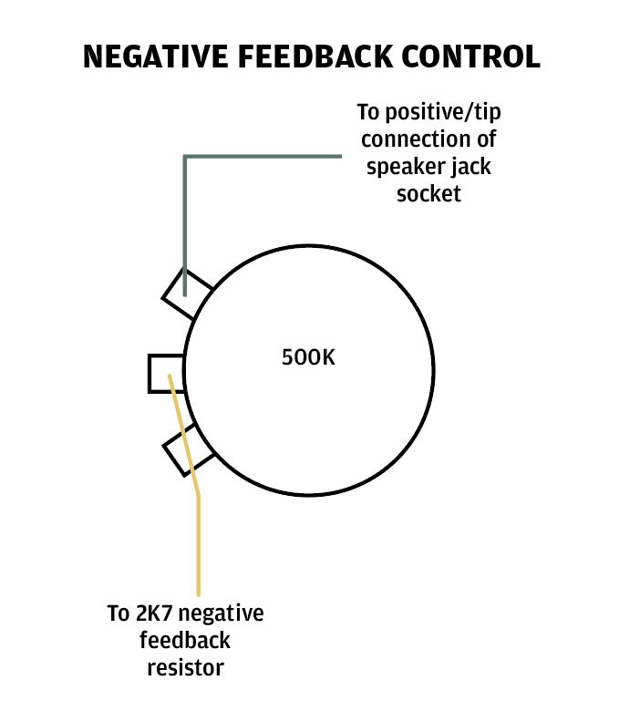
Wired this way, the feedback circuit is stock when the control is fully clockwise, and feedback is disabled with the control fully anticlockwise
Alternatively, you can remove the extension speaker jack if it’s a feature you wouldn’t use and put a toggle switch in its place. You could also drill an extra switch hole in the back panel if you want to retain the external speaker option. Schematics show the Princeton Reverb has a 2K7 feedback resistor, but the 5F11 Vibrolux and brownface Princeton have a 56k resistor.
This means more feedback is applied in the Princeton, which is one of the reasons it runs cleaner. I decided to place a 500k potentiometer in the external speaker jack socket hole to use as a variable resistor feedback control.
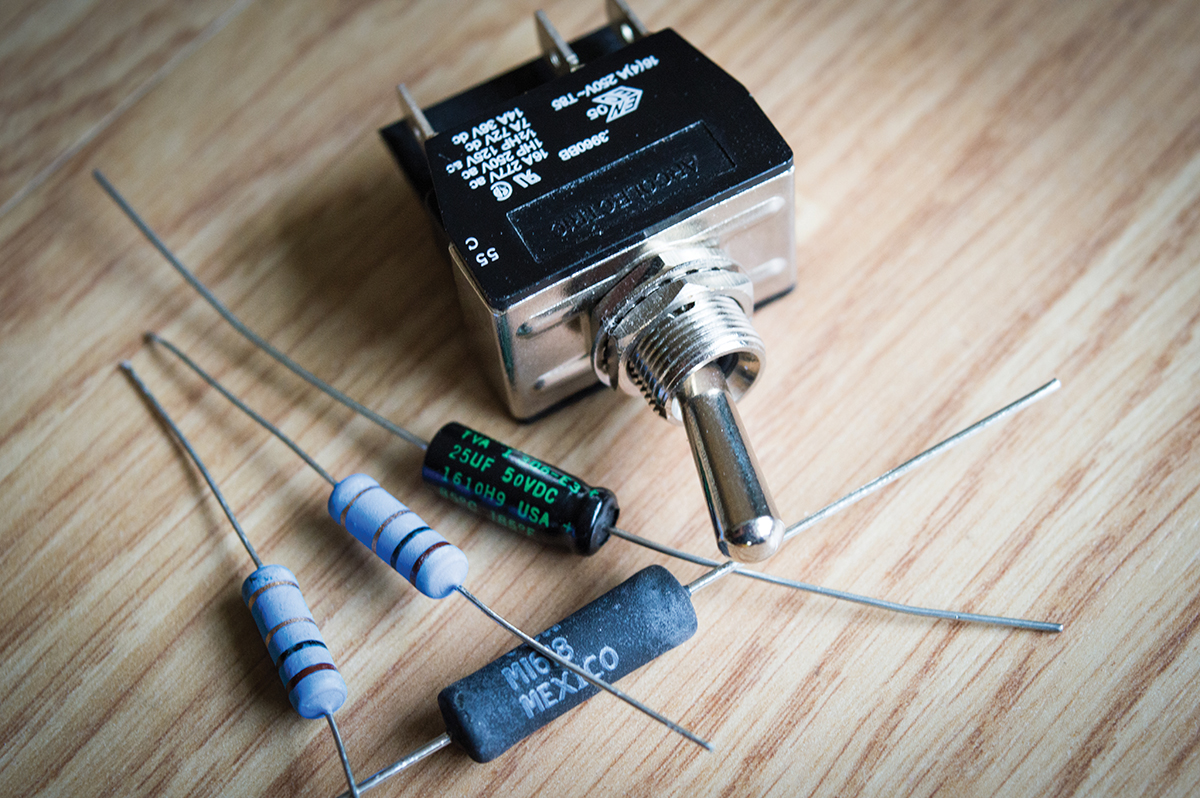
Only a handful of parts is required for bias switching, but use high-power resistors and make sure the bypass capacitor is rated at 50v or more
Fully clockwise, the feedback signal passes straight through the pot and ‘sees’ only the 2K7 resistor that remains in position on the board. Fully counter-clockwise, the 500k pot resistance combines with the 2K7 resistor to impede the feedback signal – which is tantamount to no negative feedback at all. You also get all points in between.
The effect is thicker mids and quicker overdrive. As feedback is lowered, you will also get a more compressed dynamic response and a definite softening in the low-frequency range.
You may also perceive an increase in harmonic overtones, which brightens the sound and may prompt you to set the treble control a bit lower. I generally find that lower negative feedback makes an amp feel more ‘playable’. Feel free to experiment with resistor, potentiometer and capacitor values to find your preferred settings.
The cathode-bias components are mounted onto the switch with a ground jump wire linking the left and right sides
Fixed/cathode bias
If you read our All About Rectification feature (G&B December 2016), you may recall the simplest type of valve is a diode. The only components are an anode and cathode, and so long as the anode is positively charged and the cathode is connected to ground, electrons emitted from the heated cathode will be attracted to the anode and a direct electrical current will flow.
The current flowing through a valve when no signal is present is often compared to the idle revs of a car. There is an optimum setting where the revs are high enough that the engine can tick over at rest without stalling, but not so high that the car will lurch out of control when you release the clutch. Similarly, valves must be set to optimise tone and prolong operational life. This is called biasing, and there are two main methods to bias power valves.
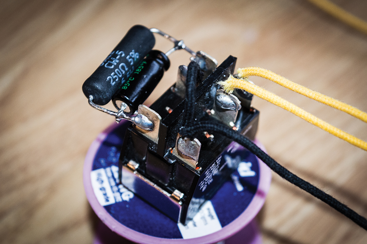
It’s easier to solder the components and wires to the switch before installing in the chassis
The first is grid biasing, and that’s the way the Princeton Reverb is configured. If you add a grid to a diode valve it becomes a triode, and by applying a fixed negative voltage to the grid we can control the current flowing within the valve when no guitar signal is present.
Setting the bias actually means fixing the negative grid voltage, and it’s done using a fixed or variable resistor. This biasing method is known as ‘fixed bias’ and the valve’s cathode is connected directly to ground. The 6V6 power valves in this amp are actually pentodes, but the explanation applies nevertheless.
Two 1-ohm, 2-watt resistors are mounted on a tag strip held to the chassis by a transformer bolt
The second method is known as cathode biasing, and the power valve’s cathode is connected to ground via a resistor rather than directly to ground. The resistor is usually wired in parallel with a capacitor, and no negative voltage is applied to the grid. Therefore, the cathode resistor determines how much current flows through the valve – and the higher the resistance, the lower the current.
Cathode biasing is seen in tweed classics such as the Deluxe and the Vox AC10, AC15 and AC30, as well as the Marshall 18W. It’s also the method chosen for the much-lauded Milkman Creamer, which is pretty much a cathode-biased Princeton Reverb. That’s the theory out of the way, so now to the business of installing a fixed/cathode bias switch in our Rift PR18.
The switch was mounted in an unused hole in the rear corner of the chassis
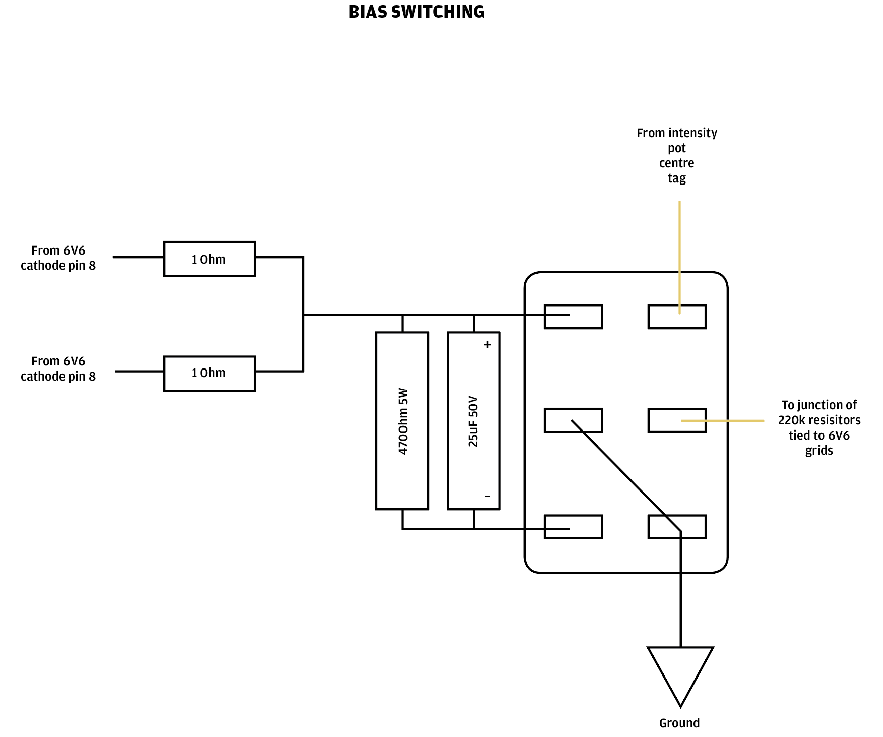
All you need is a sturdy on/on switch, a 25uF/50v capacitor, a 5W resistor and some hookup wire. Although a 250-ohm resistor is 5E3 spec, you’ll need around 470-ohm for a Princeton Reverb circuit. Simply refer to the diagram and photos. I positioned the bias switch on an existing hole on the edge of the chassis.
Flipping to cathode bias is where things get far tweedier – especially when the negative feedback is lifted. Overdrive comes on quicker, it sounds smoother and there’s more of it. The midrange also fattens up, but you will notice the low end loses some of its tightness and definition.
Tremolo tuning
If you recall, a negative voltage is applied to the power valve grids in a fixed-bias arrangement. The Princeton Reverb tremolo circuit generates an oscillating voltage that is applied to the grids in combination with the bias voltage that’s derived from the mains transformer.
This causes the grid’s negative-bias voltage to vary, which in turn affects the current flowing within the valves. In a nutshell, that’s how bias tremolo works in a fixed-bias Princeton Reverb circuit, and the valve’s ability to amplify a signal varies along with the bias fluctuations. The volume moves up and down at a constant speed, and players can adjust the speed and intensity of the effect.
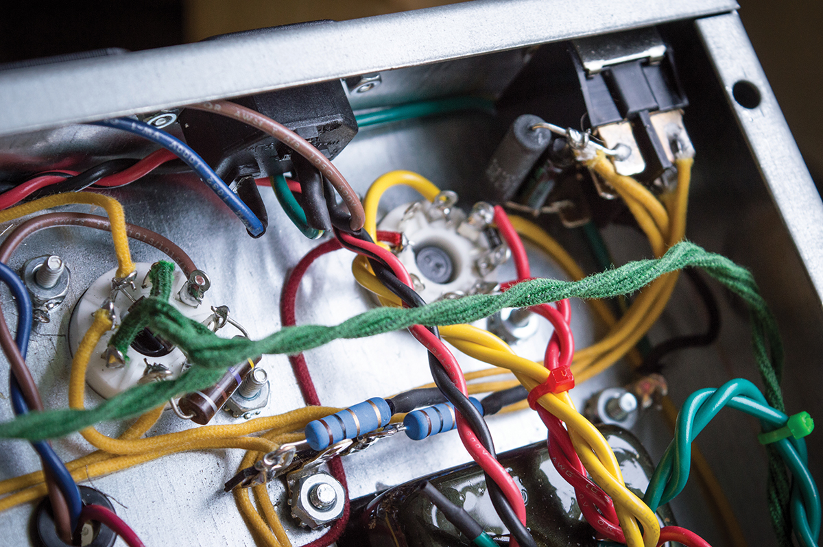
With everything in situ, the 1-ohm resistors can be used to measure the bias in fixed bias mode
Unfortunately, the tremolo’s maximum intensity decreases dramatically when the valves are switched to cathode bias – if indeed you can hear it at all. There are modifications that can be made to the stock tremolo circuit that will make the tremolo work in cathode bias mode, but as an effect it’s just about okay.
When you switch back to fixed bias mode, the tremolo becomes insanely strong. After much experimentation, I decided to live without tremolo in cathode bias mode and tweak the stock tremolo instead. Two things bothered me about the Fender-style circuit – it wouldn’t go slow enough and it lacked intensity.
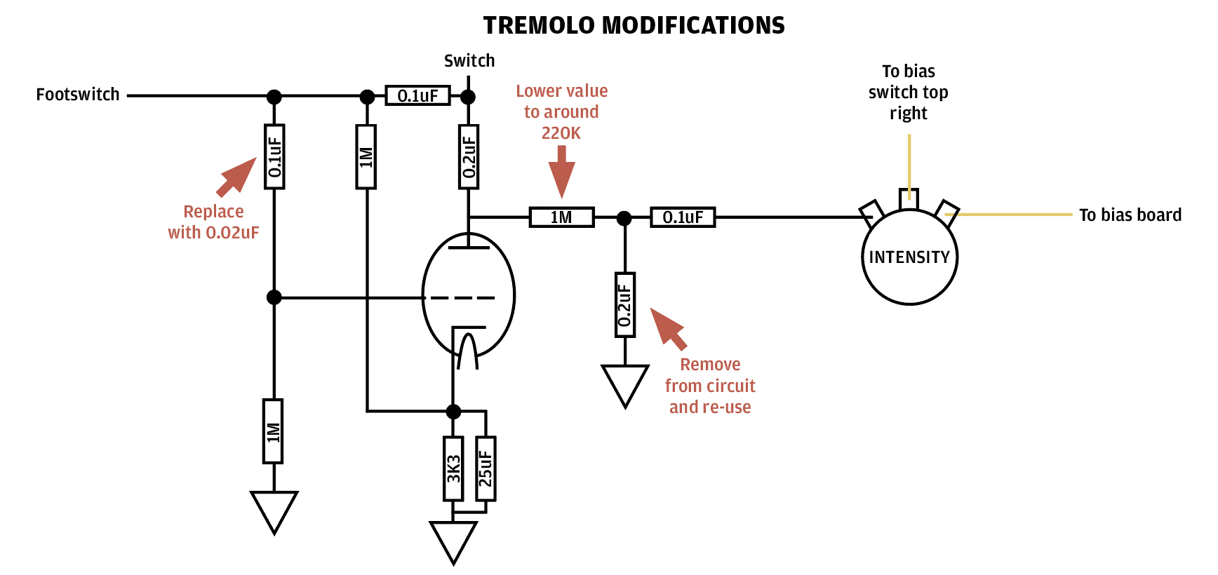
Increasing intensity is fairly easy, and I configured the Rift’s tremolo more like a brownface Princeton’s. If you compare the schematics, you’ll notice there’s a 1M resistor between the anode of the tremolo valve in a Princeton Reverb and a 0.1uF capacitor . Reducing the resistor value, or even bypassing it, dramatically increases intensity. Feel free to experiment with resistors until you hit on a value you like.
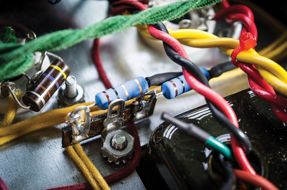
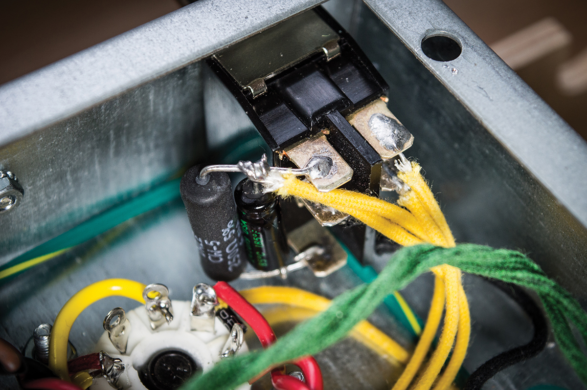
The right-side switch output connects back to the two 220k grid resistors located between the big 0.1uF signal capacitors
I went with a brownface-spec 220k, but I may up this to 330k or 470k at some point. Between the 1M resistor and 0.1uF capacitor, there’s a 0.02uF capacitor that’s tied to ground. It’s not there in the brownface trem, and de-soldering one end of the capacitor seemed to give the Rift’s trem a stronger feel. I decided to remove it, but do so carefully because it will come in useful for the next stage.
The tremolo circuit has a chain of capacitors, and the stock values are 0.01uF, 0.01uF and 0.02uF. You can slow the tremolo by swapping one or both of the 0.01uF caps to 0.02uF. I found that one change was sufficient, and I used the capacitor I removed earlier. By the time I was finished, the tremolo could sound like Bang Bang, a psychopath’s heartbeat and all points in between.
Getting a stronger and slower tremolo effect is easy with a few component changes
Final touches
Since the first instalment, something had been bugging me about the 3.3M/10pF connection where the reverb returns to the signal path. There was quite a level difference between blackface and brownface modes and the reverb mix was also a bit skewed.
There is much confusion and contradictory information about the precise purpose of these components, but it seems they are used to mix the dry and reverb signals and to prevent the reverb from feeding back on itself at high levels. Apparently, a high resistor value is necessary because it’s the only component separating the reverb’s send and return, and the 10pF capacitor is there to allow high frequencies straight through.
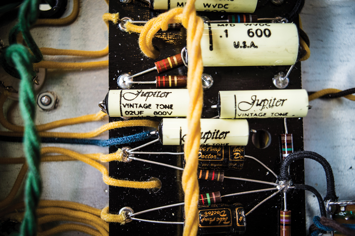
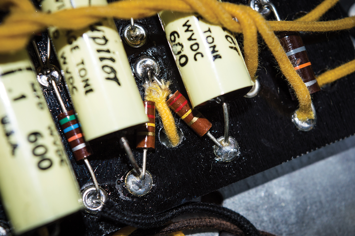
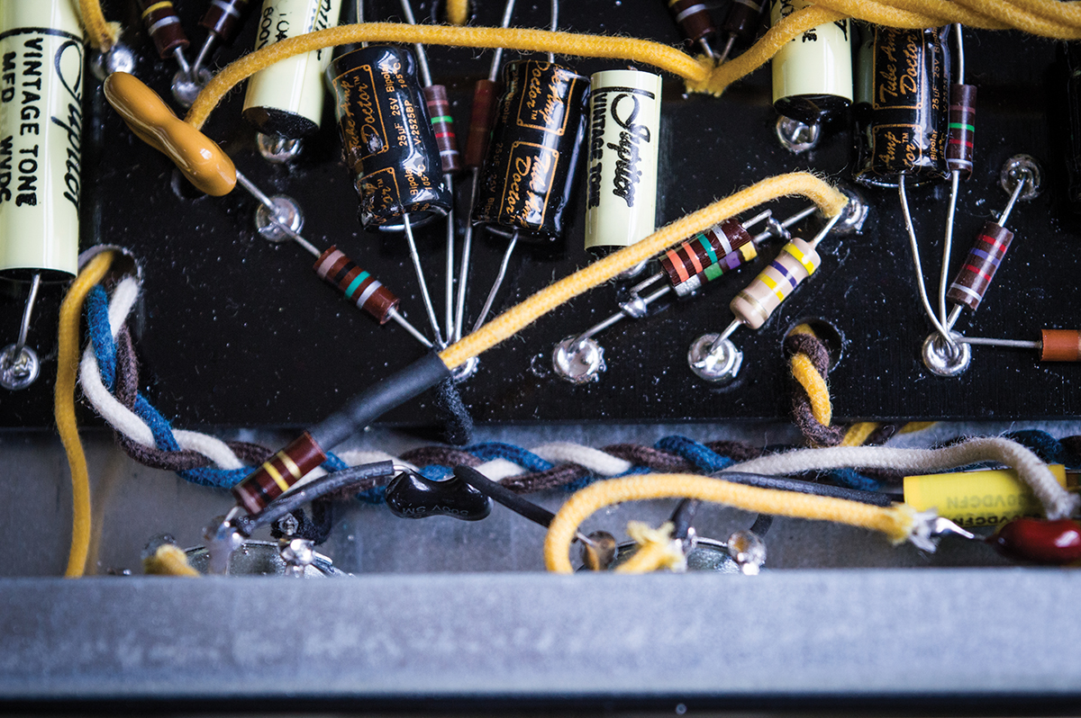
The three yellow Jupiter capacitors are part of the tremolo circuit, and we changed the one on the far right along with the 220k resistor immediately above
With the reverb send moved to a point preceding the tonestack, you can reduce the 3.3M if you want more gain in Blackface mode because there is no possibility of reverb feedback.
After another round of boutique bingo, I kept the 3M3 but settled on a 100k from the brownface stack and dispensed with the 10pF capacitor. To my ears, the levels between the tonestacks are nicely balanced, the reverb gels better with the dry signals and the treble response is more consistent.
Calling time
The sky really is the limit when you begin modding the Princeton Reverb circuit and I have only scratched the surface with this project. Although it can be fun and educational to try absolutely everything, I opted to take a more focused approach and perform only mods that addressed areas that I felt might be improved.
The stated goal was to turn this Rift PR18 into an easy-to-use general-purpose Fender-style amp by configuring it for blackface, brownface and tweed tones while retaining reverb and tremolo in every mode. In blackface mode, it’s still virtually a stock PR18 and all of this has been achieved with just a tonestack switch, a bias switch and a negative feedback control. I haven’t even drilled any holes in the chassis.
The brownface tonestack returns to the signal path through a 100k resistor, while the blackface stack retains the 3M3 resistor
This seems like a good place to stop and enjoy the amp for a while – at least until the editor decides it’s his turn once again. I do have a few other ideas that I will doubtless try at some point, so no promises but there may well be a sequel to this project.
Meanwhile, stay safe, always remove the mains plug and discharge those capacitors before touching anything inside the amp – and remember messing about with valve amps could be the death of you. Happy soldering, and once again I must thank Chris Fantana at Rift Amplification for the enthusiasm, patient help and considerable technical expertise he contributed to this project.