Related Tags
How to make your own guitar cable
Put your basic soldering skills to the test with this simple project.
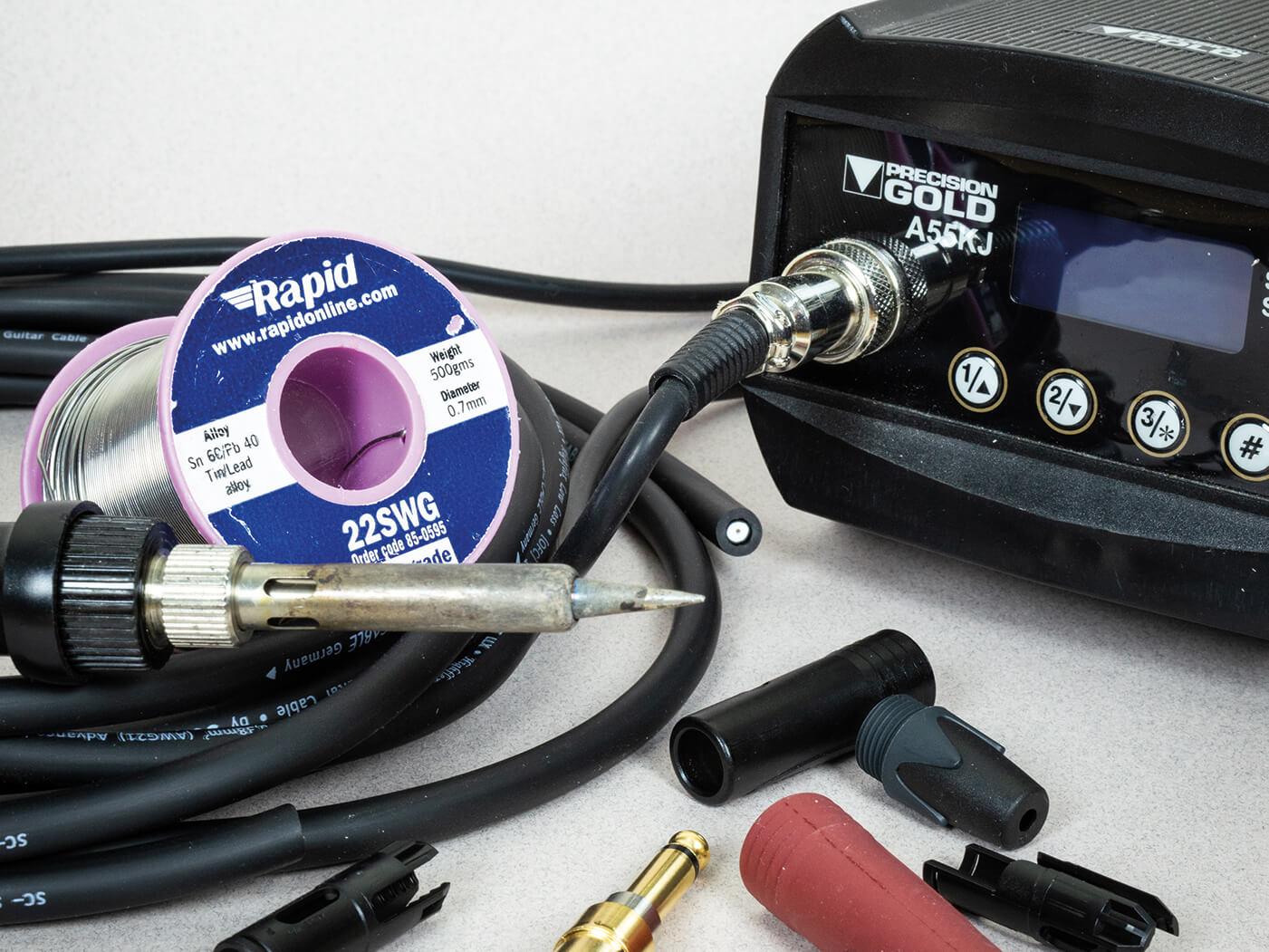
Now that you’ve covered the basics of soldering, it’s time to take on a project. If you’re new to the technique, making cables is a great way to gain experience. It’s also fairly cheap and relatively risk-free. Besides a soldering iron and some solder, all you really need is some suitable cable and a couple of quarter-inch plugs. Let’s begin:
You can’t teach an old dog Neutriks
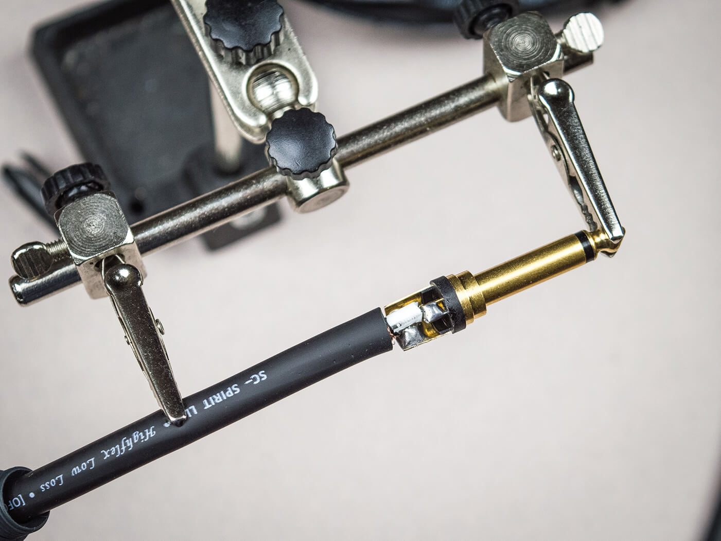
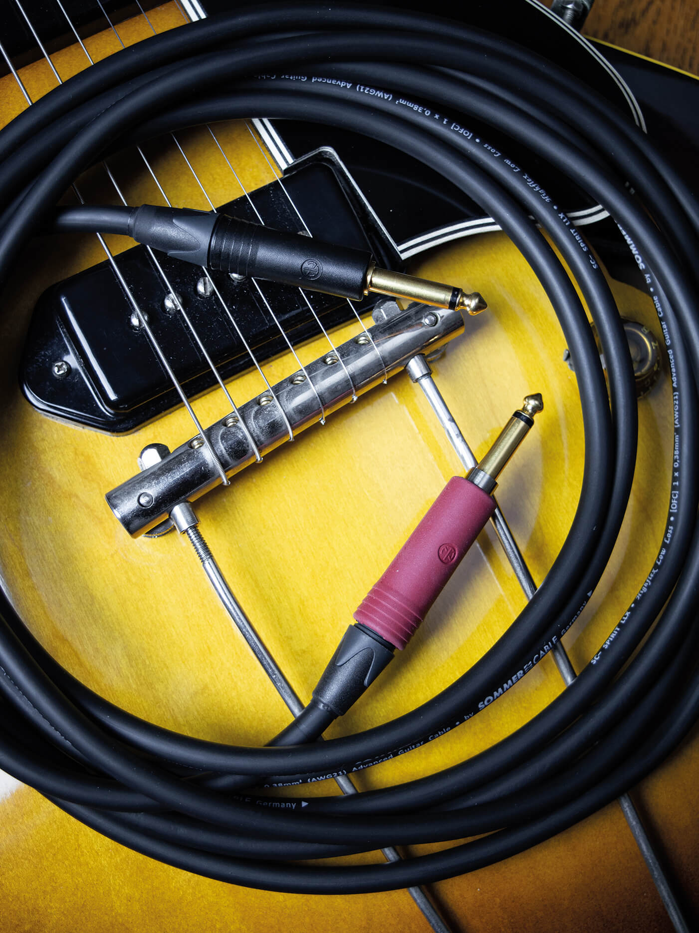
There are plenty of places to buy instrument cable and I bought the Sommer SC-Spirit LLX Low-Loss Instrument Cable used in this project from a well-known online auction site. Rather than choose by brand name or colour, I look for capacitance-per-metre and outside diameter.
Capacitance is important, because lower capacitance equates to less treble rolloff. Although some prefer the treble ‘sweetening’ effect of high-capacitance cables, others prefer transferring as much audio information as possible from guitar to amp.
The Sommer cable’s capacitance is given as 52pF per metre and as instrument cables go, that’s pretty low.
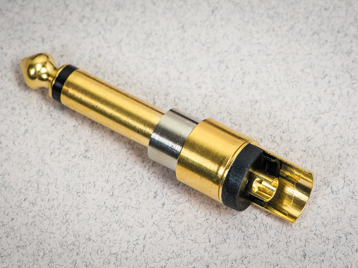
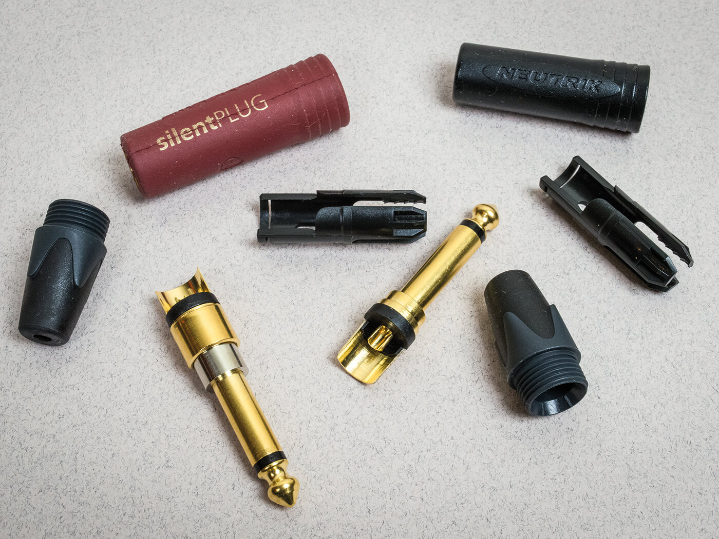
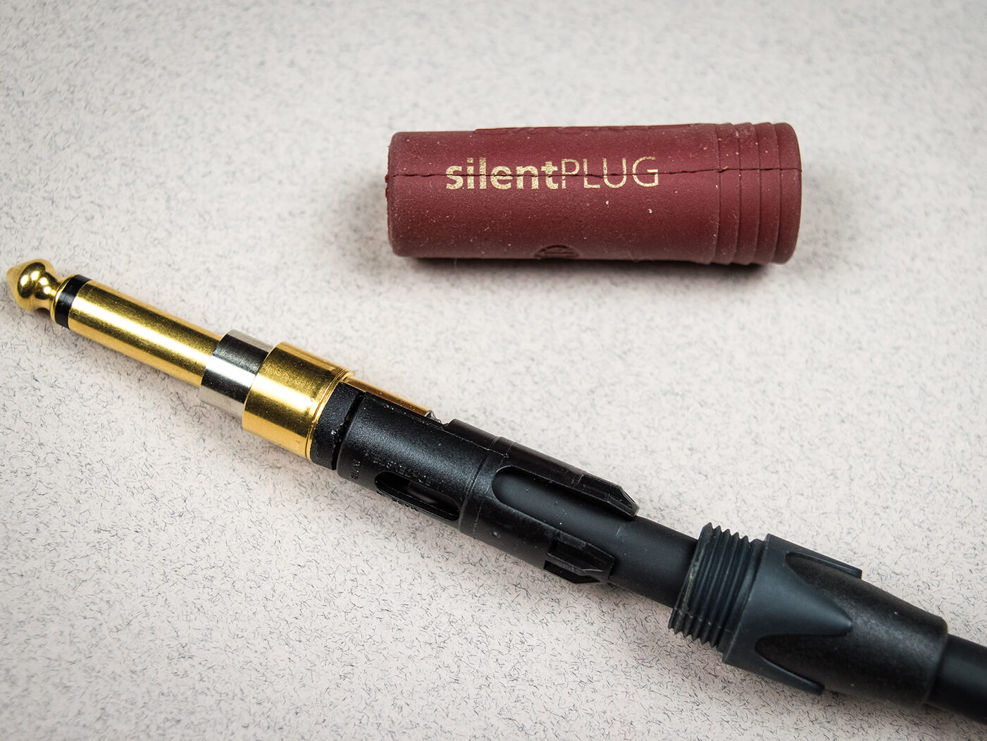
Outside diameter is a consideration because the cable has to be compatible with the plugs you plan on using. For this project, I have Neutrik plugs – an NP2X-B and an NP2X-AU. The latter is a ‘silent’ jack, which means you can plug and unplug your guitar without hearing any unwanted noise through your amp. These Neutrik plugs can accommodate cables up to 8.5mm in diameter and since the Sommer cable is 8mm, it will just fit.
On the wire
Professionals use wire strippers, but if you’re careful, you can get by with a craft knife. The first task is to strip off the black outer layer of insulation but before doing so, I push on the threaded boot that will eventually screw onto the rear of the plug. Don’t forget, otherwise you’ll have to de-solder your plug and do the whole job again.
Next, I carefully score around the cable about 15mm from the end, taking care not to cut into the braided shielding layer. The black outer layer pulls off to reveal the copper shielding. I use a small screwdriver tip to untangle the shielding wires, which are then pulled to one side and twisted together.
The centre signal wires are covered by a white plastic insulation layer, with a very thin black electrostatic shield that discharges static and keeps cables crackle-free. It’s important to strip this layer away from the exposed centre insulation.
I use a wire-stripper tool to expose about 4mm of the centre conductor, but you can use a blade instead, if you’re careful. Again, the exposed wires are twisted together and I repeat the whole procedure at the other end of the cable.
The twisted wires must be impregnated with solder – the aforementioned process also known as tinning. This is essential for achieving strong solder joints. I set my iron to about 375°C and touch the heated tip against the wires for a couple of seconds before adding the solder.
If the twisted wires are hot enough, the solder flows in quickly. But take care, because it’s easy to melt the insulation by accident if you leave the iron there too long. With all four twisted wires properly tinned, attention turns to the plugs.
Making connections

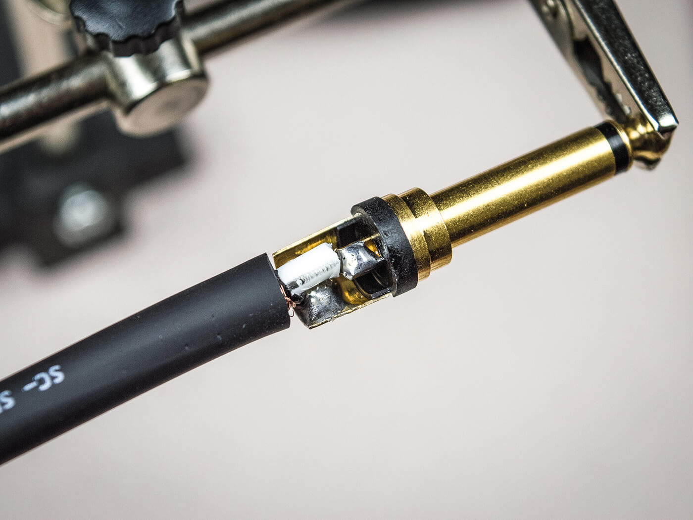
To make the solder connections as easy as possible, I apply solder to the plugs in advance. I allow the solder to flow and pool up on the surface at the back of the plugs where the shield wires will attach and the small cupped recesses where the centre wires are soldered.
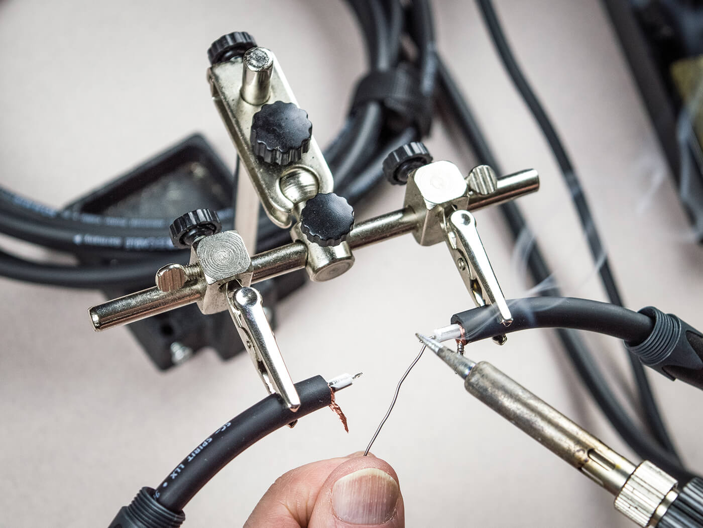
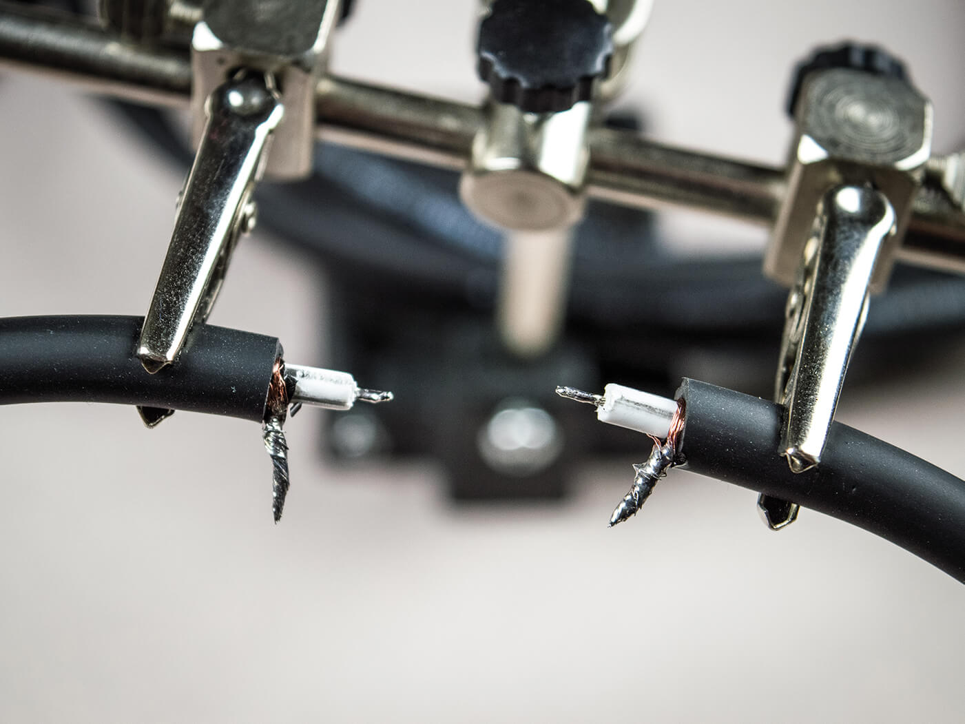
If you try holding a plug in your hand while you’re soldering onto it, you’ll burn yourself. Instead, use a vice, tape the plug onto a heat-resistant surface or use a soldering clamp with crocodile clips like the one in the pictures.
The gaps between the clips can be altered by sliding them along a bar, and this makes it very easy to position the cable and the plug while you’re making the solder joints. I ensure that I solder the shield connections first, followed by the centre wire.
Closing up
Neutrik’s instructions stipulate that the end of the plastic chuck needs to be snapped off when the cable’s outer diameter exceeds 5mm. Once done, I clip the chuck onto the cable and slide it over the solder joints. The jack’s outer cover is slipped over the plug section and the boot slides up to meet it before they are screwed together.
In the process, the chuck tightens around the cable to hold it firmly and ensure there’s never any physical strain to compromise the solder joints.
If you have made it this far, you can test your new cable using a multimeter – or simply plug it into your amp and see if it works. If it doesn’t, either one or more solder joints has failed, or the shield and signal wires are shorted. This is usually the result of stray shield wires that escaped tinning. But the chances are that it will work, and will continue to do so for many years.
Check out other DIY projects here.